16 308155
Service
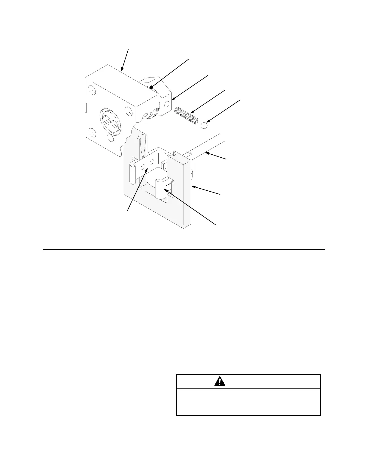
Fig. 10
31
ASSEMBLY B
26
6
7
9
29
12
ASSEMBLY A
C
D
06148
13. Lay Assembly A and Assembly B on the
workbench.
14. Slide Assembly B into the center of the tool (D),
Part No. 189305. Align the upper detent holes (C)
of the guide yoke (9) with the center line of the tool
(D). See Fig. 10.
15. Insert the spring (6) and one ball (7) into the valve
stop (26) of Assembly A. Tilt the valve stop, and
start guiding it into the tool (D), making sure the
ball is sliding into the rounded slot in the tool (D).
Place the other ball at the other end of the spring,
and push it in with your thumb while rotating the
valve stop (26) until the spring is horizontal and the
balls are in place. Continue holding this assembly
together. See Fig. 10.
16. Slide the valve stop assembly down onto the tool.
Make sure the balls (7) snap into the upper set of
holes (C) in the guide yoke (9), and the curved
ends of the guide clamp have engaged the valve
sleeve (29) groove. See Fig. 10. Slide the tool (D)
back over the rod (12) to remove it.
In steps 18 through 26, see Fig. 11.
17. Place the adapter (43) in a vise, and install the
seals as described on page 12. Install the cylinder
cap (32).
18. If the tie rods (38) were removed, reinstall them
with the short threaded end up. The other end
should be screwed about 9/16” into the bottom
cylinder cap (32).
19. Install the o-ring (49*) in the deep lower groove of
the piston (22), and install the seal (23*) over the
o-ring. Install the piston bearing (24*) around the
upper groove of the piston. Holding the piston
bearing in place to avoid damage, slide the
cylinder over the piston, and press it down.
CAUTION
When you insert the piston into the cylinder, care-
fully guide the piston seal (23*) and bearing (24*)
to prevent damaging them.