308155 7
Installation
Hydraulic Lines
NOTE: Refer to Fig. 1 to locate the parts mentioned
below.
D Shut-off valves (H and L) are installed in the
hydraulic supply and return lines. Order Part No.
108458 for 1/2 npt(f) supply lines and 108537 for
3/4 npt(f) return lines.
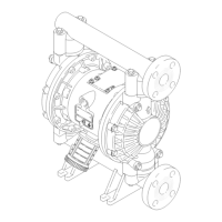
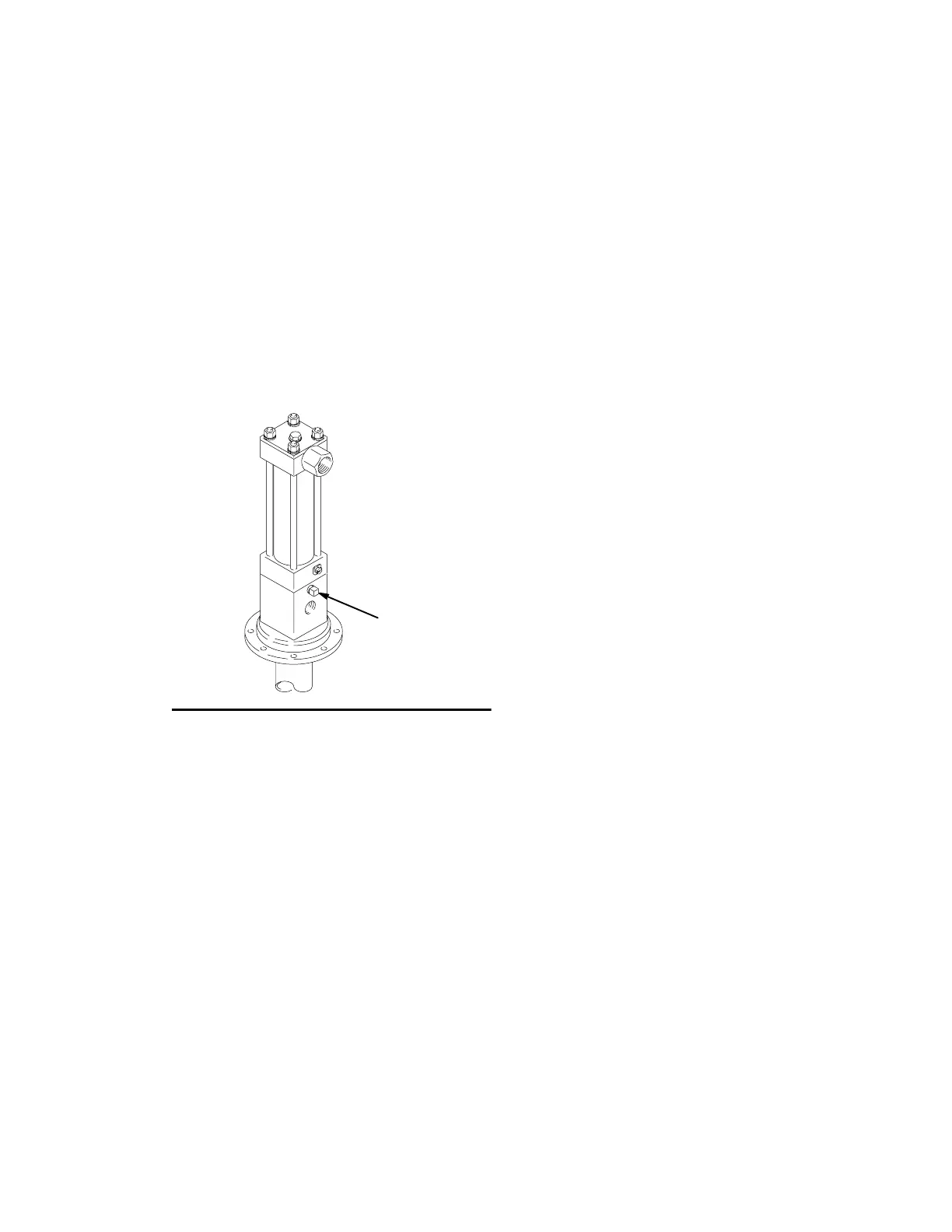
D Drain Line. Remove the plug (59) from the pump
adapter, and install a 1/8–27 npt(f) tube fitting and
weep tube (B), ending in a waste container. Monitor
the weepage of hydraulic fluid. If it seems
excessive or increases suddenly, the
reciprocator/pump seals may need to be changed.
See Fig. 2.
Fig. 2
59
06146C
D Hoses. Use a minimum 1/2” supply line (R) and
minimum 3/4” return line (F) on the reciprocator.
Contact your Graco representative for details of line
sizing.
D A pressure reducing valve (N) circulates excess
hydraulic fluid pressure back to the hydraulic power
supply. Install this valve (N) in the hydraulic supply
line with a drain hose (W) teed into the hydraulic
return line (F). Limit supply pressure to a maximum
of 1500 psi (10 MPa, 102 bar).
D An accumulator (P) reduces the hammering effect
caused by the motor when it reverses direction.
D A fluid-filled pressure gauge (M), Part No.
112567, monitors hydraulic pressure to the
reciprocator during startup. See Fig. 1. Use the
gauge for initial adjustment of the reciprocator. It
can be removed after adjustment is made.