USE EXTREME CAUTION WHEN PERFORMING THIS CALIBRATION PROCEDURE
to
reducethe risk Of afluid
WARNING
injection injury or other serious bodily injury, which can result from component rupture, electric shock, fire, eXpl0-
sion or moving parts.
I
This procedure sets the sprayer
to
2600-3000 psi NEVER attempt
to
increase the fluid Outlet pressure by
(182-210 bar)
MAXIMUM
WORKiNG
PRESSURE.
.
performing thesecalibrations inanyother.way. NEVER
EXCEED
3000
PSI (210 BAR\ MAXIMUM WORKING
Perform this procedure whenever the pressure control
PRESSURE.
Normal operatioi ofthe sprayer at higher
assembly is removed and reinstalled, or replaced,
to
pressures could result
in
component rupture, fire or
be sure the sprayer is properly calibrated.
explosion.
Improper calibration can cause the sprayer
to
over-
ALWAYS use a new
50
foot
(1 5.2 m) spray hose, rated
pressurize and result in component rupture, fire or
ex-
for at least 3000 PSI (210 BAR) MAXIMUM WORKING
plosion.
It
may also prevent the sprayer from obtaining
PRESSURE, when performing this procedure.
A
used,
the maximum working pressure, resulting in poor
under-rated hose could develop a high pressure leak
sprayer performance.
or rupture.
"~~
~
I-
~
Service Tools Needed:
NEW
50foot
(15.2
m),
3000
psi (210 bar),
0-5000
psi (0-350 bar) fluid-filled pressure gauge,
flexible nylon airless spray
hose,
Part
No.
223-541
0
NEW
spray tip, size 0.025 to
0.029
Part
NO.
102-814
318
in. ignition wrench or nut driver
5
gallon pail
of
water or mineral spirits
Swivel.
156-823
Nipple, 162-453
Tee,
104-984
Set Up
1. Follow the Pressure Relief Procedure Warnlng on
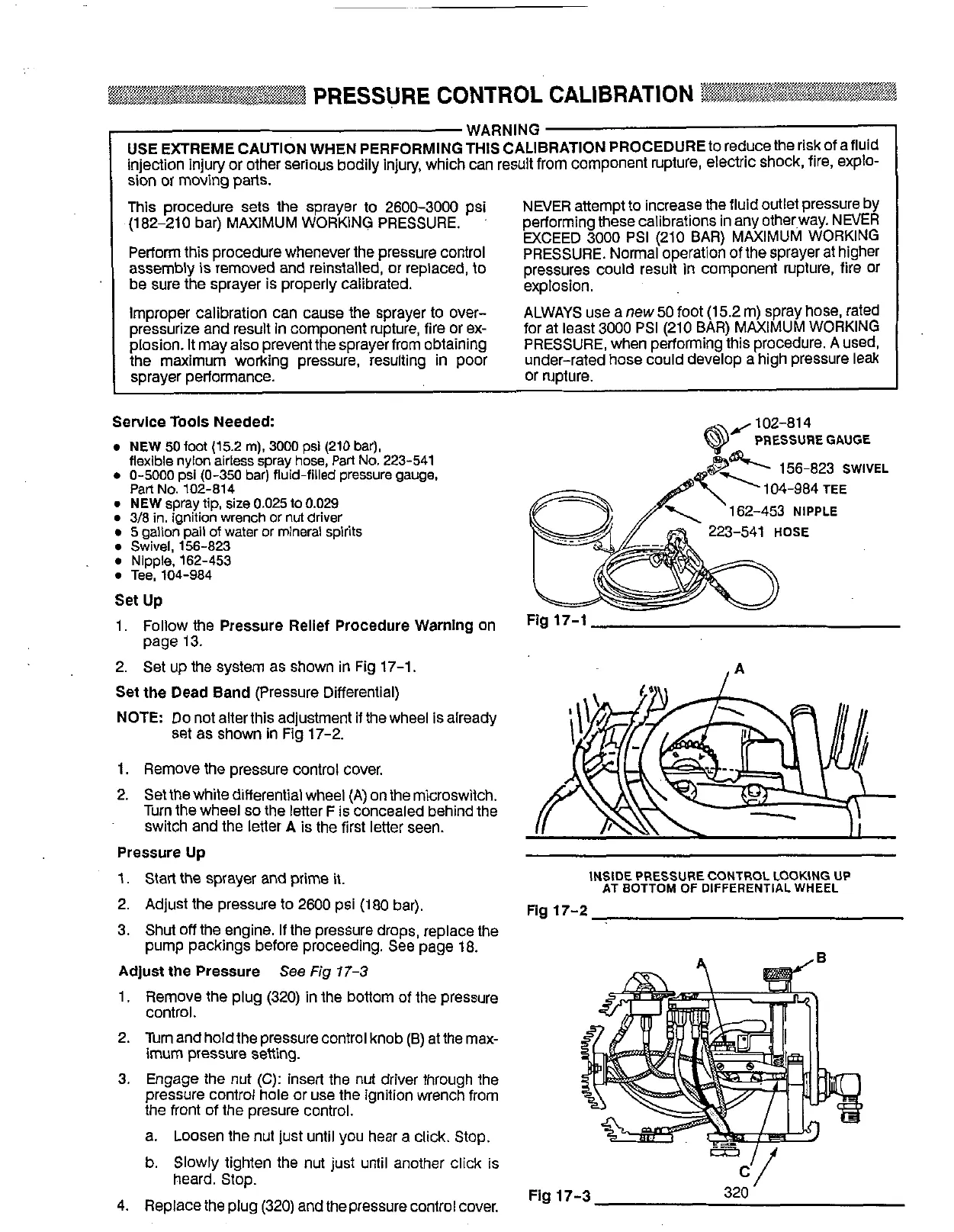
2.
Set
up
the system as shown
in
Fig 17-1.
Set the Dead Band (Pressure Differential)
NOTE
Do not alterthis adjustment
if
the wheel is already
set
as shown
in
Fig 17-2.
page 13.
1. Remove the pressure control cover.
2. Setthewhite differential wheel (A) on themicroswitch.
switch and the letter A is the first letter seen.
Turn the wheel
so
the letter
F
is
concealed behind the
Pressure Up
1.
Start the sprayer and prime
it.
2. Adjust the pressure
to
2600 psi (180 bar).
3. Shut
off
the engine. If the pressure drops, replace the
pump packings before proceeding. See page 18.
Adjust the Pressure See
Fig
17-3
1. Remove the plug (320) in the bottom of the pressure
control.
2. Turn and hold the pressure control knob (B) at the max-
imum
pressure setting.
3. Engage the nut
(C):
insert the nut driver through the
pressure control hole or
use
the ignition wrench from
the front of the presure control.
a. Loosen the
nut
just until you hear a click. Stop.
b.
Slowly tighten the nut just until another click is
4.
Replace the plug (320) and the pressure control cover.
heard. Stop.
162-453
NIPPLE
223-541
HOSE
Fig
17-1
INSIDE PRESSURECONTROL LOOKING
UP
AT BOTTOM
OF
DIFFERENTIAL WHEEL
Fig
17-2
c'/
Fig
17-3
320