~~~~~~~~~~~~~~~~~~~~
&&..,*ns;.+.&/d
~~~~,sk.sA&,~~~~~~~,~~;~
D
I
S
p
LAC
EM
E
NT
p
U
M
p
~~~~~~~~~~~~~~~~~~~~~~~~~~
,X&*.,
"
.w
%d,>*>
.,,~~~.,~~,~~~~~~~~,~:~~~~,
WARNING
5.
Tighten the
nut
(211)
onto
the rod (224) to 19 ff-lb
(25 Nm). Use
two
wrenches
to
maintain the alignment
as mentioned
in
Step 3.
sleeve.
If
the sleeve is stuck, send the cylinder
to
your Graco distributor for removal. 6. Stack the throat packings into the top of the cylinder
(219). Install the packing nut (216) loosely.
6.
Remove the sleevewhenever
your service the pump. Use
special
tool,
Part No.
222-586 only. Screw the
nut
(H)
Into
the cylinder (219).
Screw
down
the rod
(J)
to
push the sleeve
out.
See Fig
19-1.
Flg
19-1
Assembling the pump.
NOTE Use repair kit 222-588, and use all the kit parts,
for the best results. Parts included
in
the kit are
marked with an asterisk, (201
*),
in
the
text
and
drawings.
NOTE: Soak the packings in oil, and coat the rod and
inside of the cylinder with oil to prevent dam-
age during assembly..
NOTE: Alternate leather and plastic packings as
shown in Fig 1.8-3.
Be
sure the lips of the v-
packings face the direction shown. incorrect
installation damages the packings and resuits
in pump leakage.
1. Check the piston rod (224) and the inside of the sleeve
.
(218) for scoring or scratches. If these parts are dam-
2. Stack the piston packings
onto
the piston (222) as
aged, new packings will
not
seal properly.
shown in Fig 18-3 and Fig 19-2.
3.
Tighten the piston
nut (211)
onto
the
piston
to
10.5 in-lb
packings, and then
(1.2 N.m.)
to
seat the
tighten.
back
off
and finger
211
APPLY ONE
DROP
OF
SEALANT TO
THESETHREADS
Flg
19-2
Note the alignment of the piston (222) to the piston
5
and 6.
nut
(21 1) and maintain this alignment through Steps 4,
4. Apply ONE drop of adhesive, supplied with the repair
kit,
to
the piston threads. Place the ball (225')
on
the
piston. Hand tighten the piston into the rod (224) just
until the
nut
(21 1) contacts the rod. Place the flats of
~ ~~
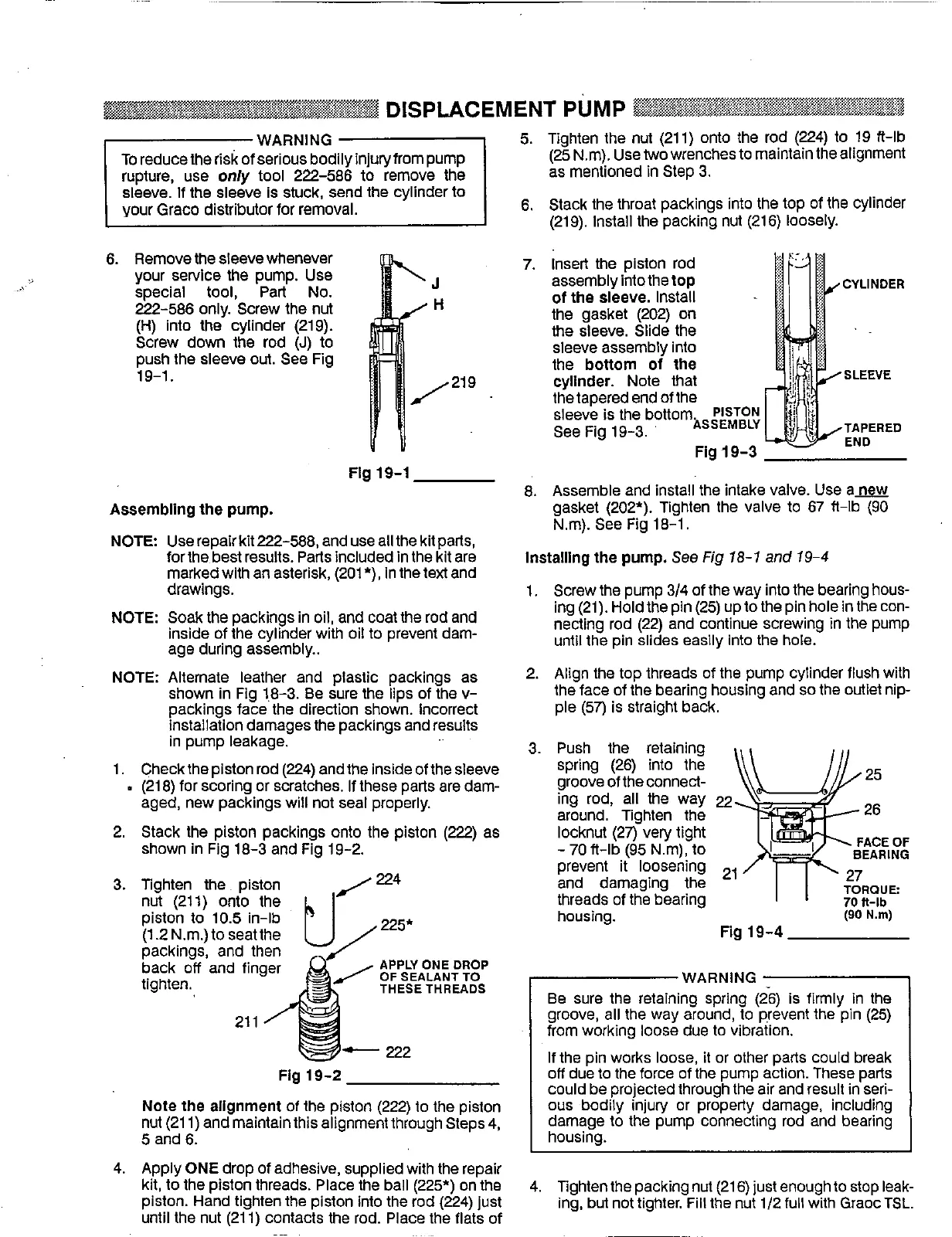
7.
Insert the piston rod
assembly into thetop
CYLINDER
of
the sleeve. Install
the gasket (202)
on
the sleeve. Slide the
sleeve assembly
Into
the bottom of the
cylinder. Note that
the tapered end of the
sleeve is the bottom&y;;
See
Fig 19-3.
TAPERED
SLEEVE
Fig
19-3
END
8.
Assemble and install the intake valve. Use anew
gasket (202'). Tighten the valve
to
67
ff-lb
(90
Nm). See Fig 18-1.
installing the pump. See
Fig
18-1 and 19-4
1. Screw the pump 3/4 of the way into the bearing hous-
ing (21). Hold the pin (25) up to the pin hole in the con-
necting rod (22) and continue screwing
in
the pump
until the pin slides easily Into the hole.
2.
Align the top threads
of
the pump cylinder flush with
the face of the bearing housing and
so
the outlet nip-
ple
(57)
is straight back.
3.
Push the retaining
spring (26) into the
groove of the connect-
ing rod, all the way
around. Tighten the
locknut (27) very tight
prevent it loosening
and damaging the
threads of the bearing
housing.
-
70
ft-lb
(95
Nm),
to
Fig
19-4
WARNING
Be
sure the retaining spring
(26)
is firmly in the
groove, all the way around,
to
prevent the pin (25)
from working
loose
due
to
vibration.
If the pin works
loose,
it
or other parts could break
off
due
to
the force of the pump action. These parts
could be projected through the air and result in seri-
ous
bodily injury or property damage, including
damage to the pump connecting rod and bearing
housing.
4. Tighten the packing nut (21
6)
just
enough
to
stop leak-
ing, but
not
tighter. Fill the nut
1/2full
with GraocTSL.
~~~~
 Loading...