ways follow the
Pressure
Relief
Proce-
the sprayer.
dure
Warning
on page
13
before repairing
NOTE:
Steps
1
to
13
refer to Fig
20-1.
1.
Refer
to
Removing
the
Pump
on
page
18.
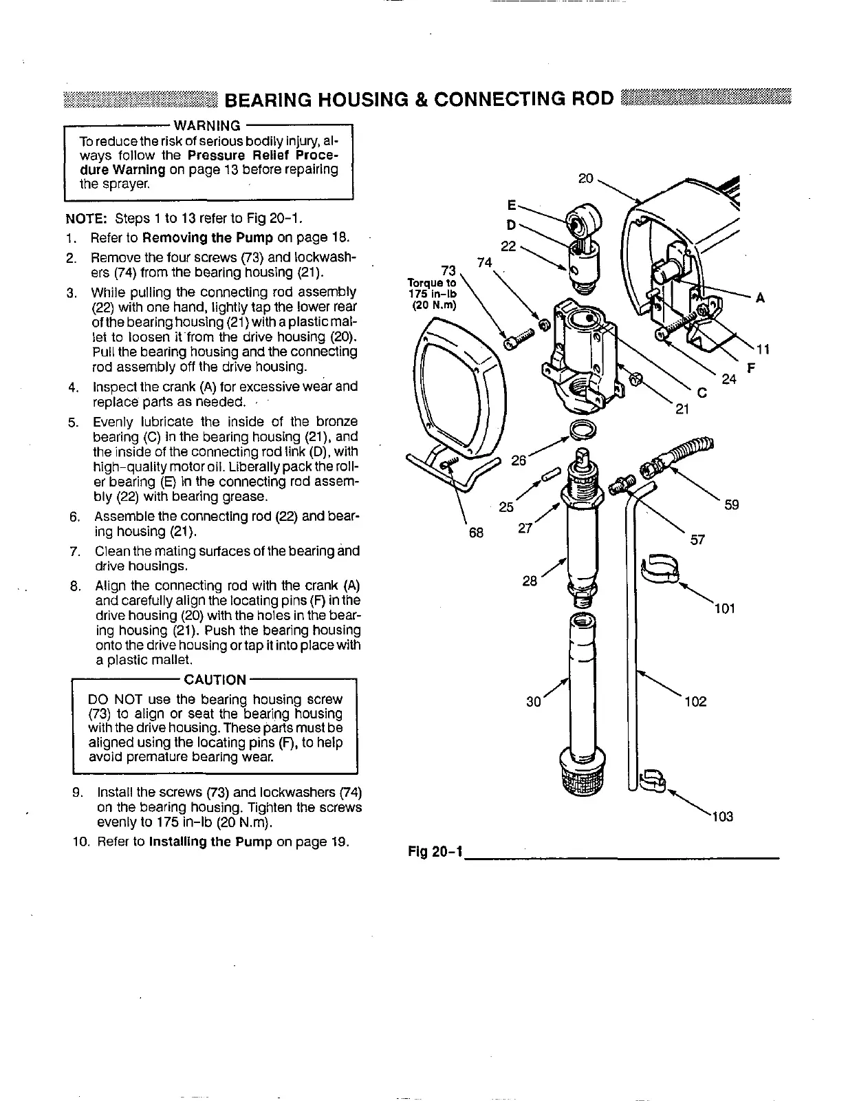
2.
Remove the four screws
(73)
and lockwash-
ers
(74)
from the bearing housing
(21).
3.
While pulling the connecting rod assembly
(22)
with one hand, lightly tap the lower rear
of the bearing housing
(21)
with a plastic mal-
let
to
loosen it’from the drive housing
(20).
Pull the bearing housing and the connecting
rod assembly
off
the drive housing.
4.
Inspect the crank (A) for excessive wear and
replace parts as needed.
.
’
5.
Evenly lubricate the inside of the bronze
the inside of the connecting rod link
(D).
with
bearing (C) in the bearing housing
(21),
and
high-qualitymotoroil. Liberallypacktheroll-
er bearing
(E)
in
the
connecting rod assem-
bly
(22)
with bearing grease.
6.
Assemble the connecting rod
(22)
and bear-
ing housing
(21).
7.
Clean the mating surfaces of the bearing and
drive housings.
8.
Align the connecting rod with the crank (A)
and carefully align the locating pins
(F)
in the
drive housing
(20)
with the holes in the bear-
ing housing
(21).
Push the bearing housing
onto the drive housing ortap it into placewith
a plastic mallet.
CAUTION
DO
NOT
use
the bearing housing screw
(73)
to
align or seat the bearing housing
with the drive housing. These parts must be
aligned using the locating pins
(F),
to
help
avoid premature bearing wear.
9.
Install the screws
(73)
and lockwashers
(74)
on the bearing housing. Tighten the screws
evenly
to
175
in-lb
(20
Nm).
10.
Refer
to
Installing the Pump
on page
19.
Fig
20-1