NOTE:
Refer
to
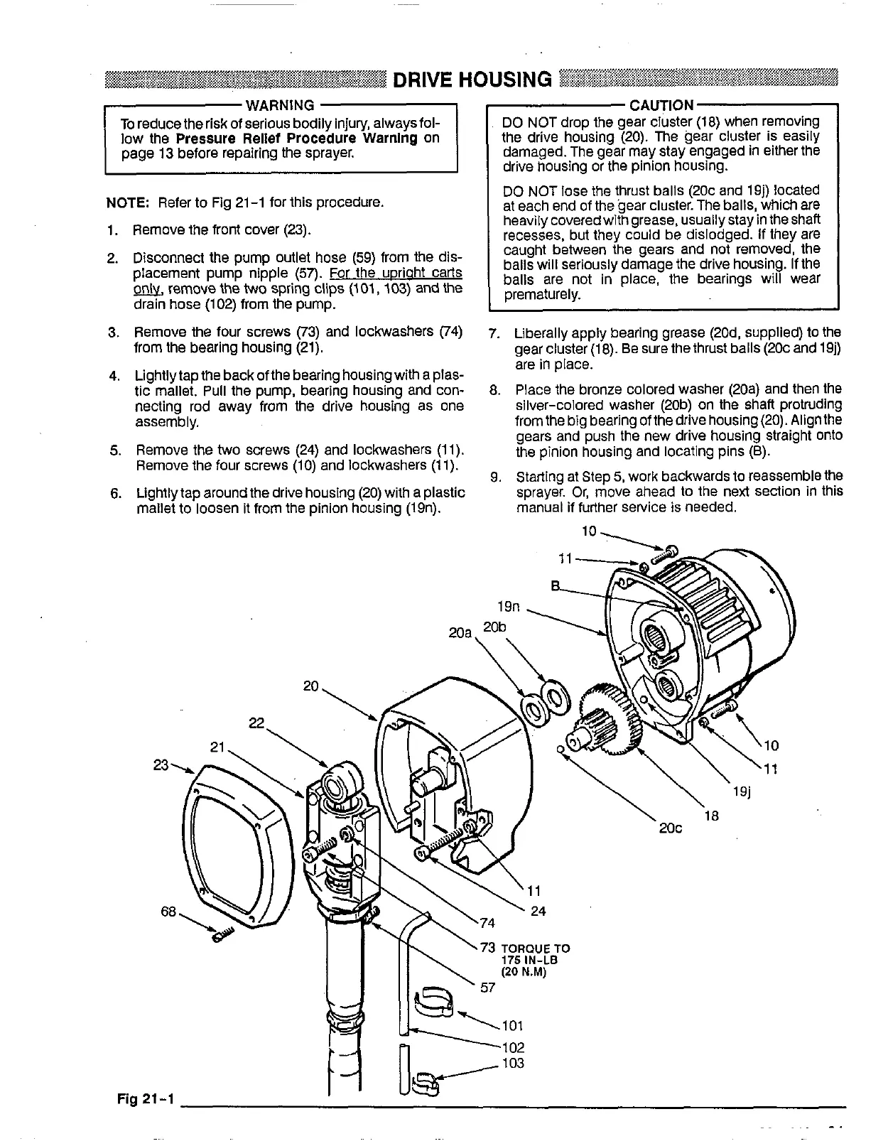
Fig 21-1 for this procedure.
1. Remove the front cover (23).
DO
NOT lose the thrust balls (20c and 19j) located
at each end of the gear cluster. The balls, which are
heaviiycoveredwithgrease,
usuallystayin the shaft
recesses, but they could be dislodged. If they are
caught between the gears and
not
removed, the
Placement Pump nipple
(57).
For the UDriaht carts
balls
are
not
in
place, the bearings wear
2.
Disconnect the
pump
Outlet
hose
(59)
from
the
dis-
balls will seriously damage the drive housing,
If
the
a,
remove the two
spring
clips (101,
103)
and the
drain hose (102) from the pump.
prematurely,
3. Remove the four screws (73) and lockwashers (74)
7.
Liberally apply bearing grease (20d, supplied)
to
the
from the bearing housing (21). gear cluster (1 8).
Be
sure the thrust balls (20c and 19j)
4. Lightlytap the back of the bearing housing with a plas-
are
in
place.
tic mallet. Pull the pump, bearing housing and con- 8. Place the bronze colored washer (20a) and then the
necting rod away from the drive housing as
one
assembly. from the big bearing
of
the drive housing (20). Alignthe
silver-colored washer (20b)
on
the shaft protruding
5.
Remove the
two
screws (24) and lockwashers (1
1).
the pinion housing and locating pins
(8).
gears and push the new drive housing straight Onto
Remove the four screws
(1
0)
and lockwashers (1 1).
6.
Lightlytap around the drive housing (20) with a plastic
9.
Starting at Step
5,
work backwards
to
reassemble the
mallet
to
loosen it from the pinion housing (19n).
sprayer. Or, move ahead
to
the
next
section
in
this
manual if further sewice
is
needed.
10
73
TORQUE TO
Fig
21-1
 Loading...