'~~~~~~~~~~~,~~~~~~~~~~~~~~~~~~~~~~~~~~~~~~~~
,~:,:~:,~:,~~~~~~~~~~~~~~;~~~~~~~~~~~~~~~~~~~~~~~~~~~~~~~~~~~~~~~~~
CLUTCH
~~~~~~~~~~~~~~~~~~~~~~~~~~~~~~~~~~~~~~~~~~~~,~~,~,~~~~~
.~
~~~~~~~~~~;~~~~~~~~~~:~~~~~~~~~~~~~~~?~~~~:~
,.::
..,,,,
*,,"~.,~
,~~i.r
NOTE
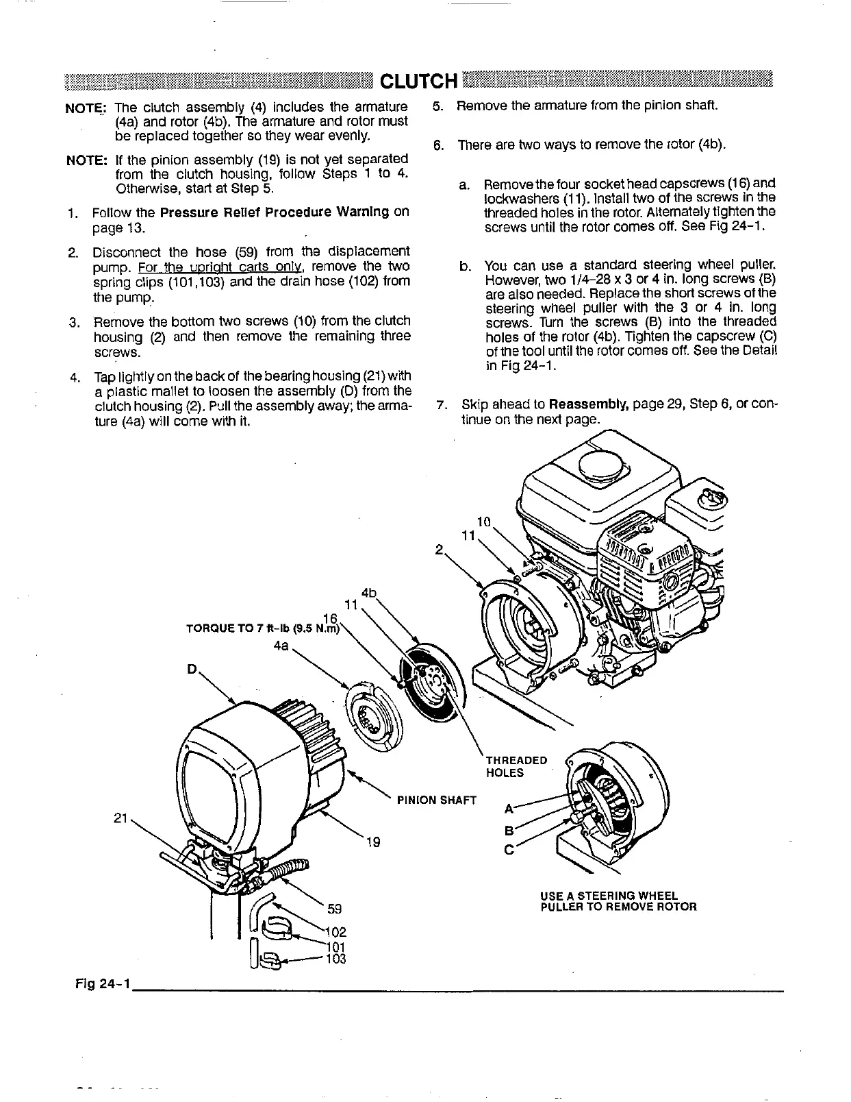
The clutch assembly (4) includes the armature
5.
Remove the armature from the pinion shaft.
be replaced together
so
they wear evenly.
(4a) and rotor (4b). The
armature and rotor must
NOTE: If the pinion assembly (19) is
not
yet separated
from the clutch housing, follow Steps 1
to
4.
Otherwise, start at Step
5.
a. Removethe four socket head capscrews (1
6)
and
lockwashers (1 1). Install
two
of the screws in the
1. Follow the
Pressure
Relief
Procedure
Warnlng
on
threaded holes in the rotor. Alternately tighten the
page 13. screws until the rotor comes
off.
See
Fig 24-1.
2. Disconnect the hose (59) from the displacement
pump. For the uDriaht carts only, remove the
two
spring clips (101,103) and the drain hose (102) from
b.
You
can
use
a standard steering wheel puller.
However,
two
1/4-28
x
3
or 4
in.
long screws
(B)
the pump. are also needed. Replace the short screws of the
3. Remove the bottom
two
screws (10) from the clutch
steering wheel puller with the
3
or 4
in.
long
screws. Turn the screws
(B)
into the threaded
housing (2) and then remove the remaining three holes of the rotor (4b). Tighten the capscrew
(C)
screws. of the tool until the rotor comes
off.
See the Detail
6.
There are
two
ways
to
remove the rotor (4b).
4. Tap lightly
on
the back of the bearing housing (2l)with
a plastic mallet
to
loosen the assembly
(D)
from the
ture (4a) will come with it.
clutch housing
(2).
Pull
the assembly away; the arma-
7.
Skip ahead
to
Reassembly,
page 29, Step
6,
Or Con-
in Fig 24-1.
tinue
on
the next page.
21
USEA STEERING WHEEL
PULLER
TO
REMOVE
ROTOR
Fig
24-1