30886812
On/Off Switch
Removal
1.
Relieve pressure; page 4.
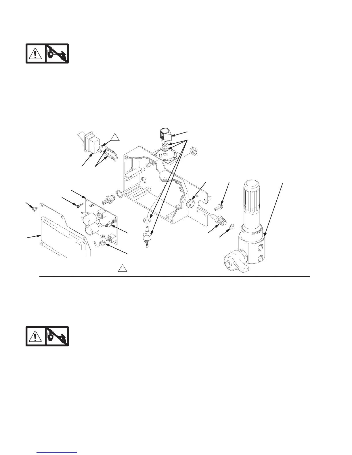
2. Fig. 15. Remove five screws (307) and
cover (322).
3. Disconnect two wires (A) from ON/OFF
switch (309).
4. Press in on two retaining tabs on each side of
ON/OFF switch (309) and remove switch.
Installation
1. Install new ON/OFF switch (309) so tabs of switch
snap into place on inside of pressure control
housing.
2. Connect two wires (A) to ON/OFF switch.
3. Install pressure control cover (322) with five
screws (307).
Fig. 15
322
307
A309
302
303
E
D
313
310
318z
318aa
318a
Locate switch terminals as shown
315 319
Pressure Control
Control Board
Removal
1.
Relieve pressure; page 4.
2. Fig. 15. Remove five screws (307) and
cover (322).
3. Fig. 22. Disconnect at control board (302):
Four clutch leads: two violet and two black.
Lead (D) from potentiometer.
Lead (E) from transducer.
Two red leads (A) to ON/OFF switch (309).
4. Fig. 15. Remove five screws (303), green ground
wire and control board (302).
Installation
When installing replacement control board, follow
instructions with control board to set model type.
1. Fig. 15. Install green ground wire and control
board (302) with five screws (303).
2. Fig. 22. Connect to control board (302):
Two red leads (A) to ON/OFF switch (309).
Lead (E) to transducer.
Lead (D) to potentiometer.
Four clutch leads: two violet and two black.
3. Fig. 15. Install cover (322) with five screws (307).