308868 13
Pressure Control Transducer
Removal
1.
Relieve pressure; page 4.
2. Fig. 15. Remove five screws (307) and
cover (322).
3. Disconnect lead (E) from control board (302).
4. Remove three screws (319) and fluid filter (318)
from control plate (301). Carefully pull transducer
connector through rubber grommet (315).
5. Remove pressure control transducer (318z) and
packing o-ring (318aa) from filter housing (318a).
Installation
1. Fig. 15. Install packing o-ring (318aa) and pres-
sure control transducer (318z) in filter
housing (318a). Torque to 30–35 ft-lb.
2. Carefully feed transducer connector through
rubber grommet (315). Install fluid filter (318) on
control plate (301) with three screws (319).
3. Connect lead (E) to motor control board (302).
4. Install cover (322) with five screws (307).
Pressure Adjust Potentiometer
Removal
1.
Relieve pressure; page 4.
2. Fig. 15. Remove five screws (307) and
cover (322).
3. Disconnect lead (D) from control board (302).
4. Loosen set screws on potentiometer knob (313)
and remove knob, shaft nut, lockwasher (310) and
pressure adjust potentiometer (310).
5. Remove seal (311) from potentiometer (310).
Installation
1. Install seal (311) on potentiometer (310).
2. Fig. 15. Install pressure adjust potentiometer
(310), shaft nut, lockwasher (310) and potentiome-
ter knob (313).
a. Turn potentiometer shaft (310) clockwise to
internal stop. Assemble potentiometer knob
(313) to strike pin on plate (312) and have
bottom of knob clear plate by .040 to .060 in.
b. After adjustment of step a., tighten both set
screws in knob 1/4 to 3/8 turn after contact
with shaft.
3. Connect lead (D) to control board (302).
4. Install cover (322) with five screws (307).
Control Board Diagnostics
1. Fig. 15. Remove five screws (307) and
cover (322).
2. Start sprayer.
3. Turn ON/OFF switch ON.
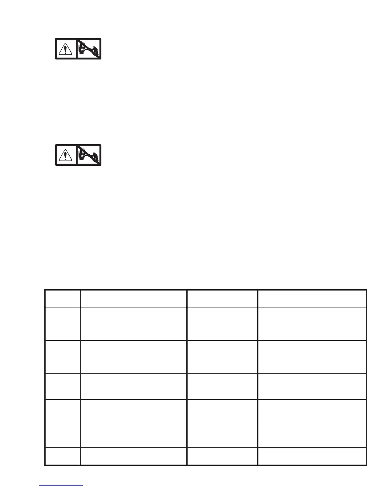
4. Observe LED operation and reference following
table:
LED
BLINKS
SPRAYER OPERATION INDICATES WHAT TO DO
Two times
repeatedly
Sprayer shuts down and LED contin-
ues to blink two times repeatedly
Run away pressure.
Pressure greater than
4500 psi (310 bar, 31
MPa).
1. Check pressure transducer con-
nection at control board
2. Replace pressure transducer
3. Replace control board
Three
times re-
peatedly
Sprayer shuts down and LED contin-
ues to blink three times repeatedly
Pressure transducer is
faulty or missing
1. Check pressure transducer con-
nection at control board
2. Replace pressure transducer
3. Replace control board
Four times
repeatedly
Sprayer shuts down and LED contin-
ues to blink four times repeatedly
Generator voltage is
low
1. Increase engine throttle
2. Check wiring connections
3. Service Honda engine alternator
Five times
repeatedly
Sprayer shuts down and LED contin-
ues to blink five times repeatedly
High clutch current 1. Check clutch 5-pin bulkhead con-
nector. Clean contacts.
2. Measure 1.2 0.2Ω
(GMax3900); 1.7 0.2Ω (GMax
5900) across clutch field at 70F
3. Replace clutch field assembly
Six times
repeatedly
Sprayer shuts down and LED contin-
ues to blink six times repeatedly
High clutch temperature Replace clutch armature and rotor