DISPLACEMENT
PUMP
REP
AIR
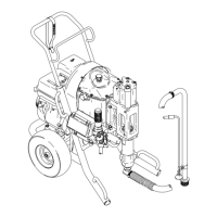
Disassembly
NOTE: For this procedure, see Fig 10 for Model
208–916
and Fig 11 for Model 221–072
1. Screw
the extension tube (80) or suction
tube
union off the intake valve housing (99). Re-
move
the retaining
ring (78) and strainer (79)
from
the extension tube and put them in a pail
of
clean solvent. See page 20.
2. Unscrew
the intake valve housing (99) and
re
-
move
all parts.Clean the parts with solvent. In
-
spect
the carbide seat; replace the housing
if
the
seat is worn or damaged. If no further ser
-
vice
is needed, reassemble the intake valve.
3. Disconnect the displacement rod (103). See
HYDRAULIC MOT
OR REMOV
AL
, page 14.
4. Remove the cover (59). Loosen the packing
nut (102). Push the displacement rod (103)
down
and pull
it and the piston out the bottom
of
the housing (101).
NOTE: If
the rod
(103) is stuck due to dried fluid,
remove the packing nut (102). Fill the
packing
cavity with solvent and let it soak
to
free the rod.
5. Unscrew
the piston stud (100) and remove the
packings,
glands, etc.
6. Screw the packing nut (102) out of the pump
housing
(101). Remove
the packings, glands,
etc.
7. Clean
all parts with solvent and inspect them.
Replace
worn or damaged parts, paying par
-
ticular
attention to the carbide seat on the pis
-
ton
stud.
8. Inspect
the outer surface of the displacement
rod (103) and the inner surface of the sleeve
(90)
for scratches or scoring which could dam
-
age
the packings and cause the
pump to leak.
To replace a sleeve (90), contact your Graco
representative. The new sleeve must be in-
stalled
with the tapered end down.
Reassembly Notes
1. Repair
kits are available for the
pumps. Use all
the
parts in the kit for the best results.
Pump Model 208–916: use kit 208–919.
Parts included in this kit are marked with an
asterisk,
i.e. 85* in the text and drawings. See
Fig
10.
Pump Model 221–072: use kit 223–664.
Parts included in this kit are marked with a
dagger,
i.e.
85
, in the text and drawings. See
Fig
1
1.
2. Lubricate all packings before installing them.
Make
sure the lips of the v–packings are fac
-
ing against the fluid pressure.
Fig 10
59
68
13
102
15
*96
*98
103
*85
91
100
101
93
86*
99
CARBIDE
SEAT
97
*94
CARBIDE
SEAT
TORQUE
T
O
75–100 ft–lb
(96–135 N.m)
TORQUE TO
65–75 ft–lb
(88–96 N.m)
HYDRAULIC
MOTOR
PISTON ROD
USE WRENCHES
ON FLA
TS ONL
Y
Model
208–916
See
Model 221–072 on page 17
TORQUE
T
O
15–25 ft–lb
(20–34 N.m)
90
T
APERED END DOWN
84
92
88
LIPS OF THROA
T
V–P
ACKINGS MUST
FACE DOWN
96
98
88
92
LIPS OF THROA
T
V–P
ACKINGS MUST
F
ACE UP
96
98
 Loading...