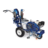
Engine
16 311020Y
Engine
Removal
1 Remove Pinion Assembly/Clutch
Armature/Clamp and Clutch Housing. See pages
11-15.
2 Fig. 12. Remove clip (251) and junction box (226).
3 Fig. 11. Disconnect all necessary wiring.
4 Fig. 12. Remove screw (177). Remove two screws
(117), lock nuts (118), and ground conductor (230,
260) from base of engine (185).
5 Lift engine carefully and place on work bench.
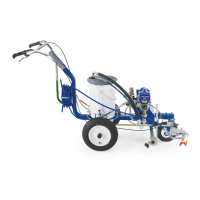
Installation
1 Lift engine carefully and place on cart.
2 Fig. 12. Install two screws (117) and ground conductor
(223, 260) in base of engines and secure with lock nuts
(118). Torque to 20 to 30 ft-lb.
3 Fig. 11. Connect all necessary wiring.
4 Install Pinion Assembly/ Clutch Armature/Clamp and
Clutch Housing. See pages 11-15.
NOTICE
All service to the engine must be performed by an
authorized HONDA dealer.
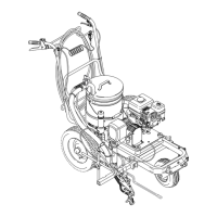
Main Control Box Cable
Wheel Sensor Cable
Bottom View
To Engine
ti6397a
TO MAIN
CONTROL
BOX
DISTANCE
SENSOR
TO
ENGINE
JUNCTION
BOX
PUMP STROKE
COUNTER
CLUTCH
En g i n e
ti25625a
Fig. 12
 Loading...