
G
Gordon CoffeyAug 21, 2025
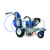
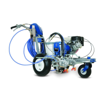
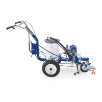
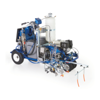
How to troubleshoot starting issues with my Graco Construction Equipment?
- Aamy55Aug 21, 2025
If your Graco Construction Equipment engine or sprayer won’t start, first, ensure the engine switch is turned on. If it still doesn't start, check the gas tank and refill if empty. Also, verify the engine oil level and replenish if low. Make sure the spark plug cable is correctly connected and not damaged; reconnect or replace the spark plug if needed. Finally, if there is frozen water in the sprayer, allow it to thaw completely before attempting to start.