EasyManua.ls Logo

Graco LineLazer V HP Auto Series - User Manual

Graco LineLazer V HP Auto Series
30 pages
Print Icon
To Next Page IconTo Next Page
Loading...
3A8102A
EN
Application Methods
Parking Lot Layout for LineLazer
V
HP Auto Series with LazerGuide
2000
For the application of line striping materials. For professional use only. For outdoor use
only. Not for use in explosive atmospheres or hazardous locations.
Maximum Operating Pressure: 3300 psi (22.8 MPa, 228 bar)
Important Safety Instructions
Read all warnings and instructions in this manual and in related manuals.
Be familiar with the controls and the proper usage of the equipment.
Save these instructions.
Question and Answer IconNeed help?

Do you have a question about the Graco LineLazer V HP Auto Series and is the answer not in the manual?

Summary

Important Safety Information

LineLazer V Auto-Layout System Introduction

Gun Setup Configuration

Configuration of spray guns for optimal parking lot layout applications.

Stall Calculator Offset Setup

Procedure to input and store offset values in the Stall Calculator for future use.

System Calibration

Calibration Procedure

Steps to calibrate the LineLazer V Auto-Layout System using a 24 ft precision course.

Measure Mode Operation

Using the Measure Mode

How to use the Measure Mode to mark specific distances on the LiveLook display.

Basic Stall Layout

Layout Mode: Establishing Reference Dots

Procedure for establishing START and FINISH reference dots for basic stall layouts.

Stall Calculator: Measuring Stall Sizes

Measuring and calculating desired stall sizes for basic stall layouts.

Layout Mode: Marking Stall Beginnings

Procedure for marking dots at the beginning of each stall in basic stall layouts.

Stall Calculator: Marking Curb Dots

Procedure for marking dots near the curb for basic stall layouts.

Striping Mode: Connecting Basic Stall Dots

Connecting the laid dots with paint lines for basic stall layouts.

Island Stall Layout

Layout Mode: Establishing Island References

Establishing START/FINISH reference dots for island stall layouts.

Stall Calculator: Measuring Island Sizes

Measuring and calculating desired stall sizes for island stall layouts.

Layout Mode: Placing Stall Line Dots

Placing dots at the beginning and end of each stall line for island layouts.

Striping Mode: Connecting Island Stall Dots

Connecting dots with paint lines for island stall layouts, including skip-line feature.

Radius Stall Layout

Layout Mode: Establishing Radius References

Establishing perimeter reference lines for the start of radius stalls.

Stall Calculator: Measuring Inner Radius

Measuring the inner radius distance for radius stall layouts.

Layout Mode: Marking Stall Ends

Marking dots at the end of each stall for radius stall layouts.

Stall Calculator: Measuring Outer Perimeter

Measuring the outer perimeter distance for radius stall layouts.

Layout Mode: Placing Spaced Radius Dots

Placing evenly spaced dots at the beginning of each stall for radius layouts.

Striping Mode: Connecting Radius Stall Dots

Painting lines by connecting dots for radius stall layouts.

Angle Stall Layout

Parking Mode: Establishing Angle References

Establishing START/FINISH reference dots for angle stall parking layouts.

Angle Calculation Setup

Setting up the LiveLook display for angle calculation in angle stall layouts.

Layout Mode: Marking Angle Stall Dots

Marking dots at the end of each stall for angle stall layouts.

Striping Mode: Connecting Angle Stall Dots

Connecting dots with paint lines for angle stall layouts.

Cross Hatch Layout

Layout Mode: Establishing Cross Hatch Boundary

Establishing boundary and applying dots at desired spacing for cross hatch patterns.

Striping Mode: Painting Interior Hatch Lines

Painting interior lines by connecting dots for cross hatch patterns.

Striping Mode: Painting Perimeter Hatch Lines

Painting perimeter lines by connecting dots for cross hatch patterns.

Marker Mode Layout

Center Lines and Lane Lines Mode

Painting lines for center and lane layouts using reflective markers.

Graco Standard Warranty

Warranty Terms and Conditions

Details of Graco's standard warranty for equipment, including limitations and exclusions.

Graco Information and Support

Product Information and Ordering

Information on obtaining the latest product details, patents, and placing orders.

Overview

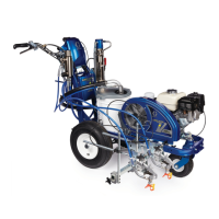
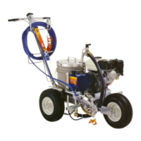
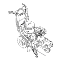
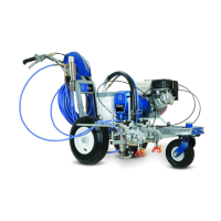
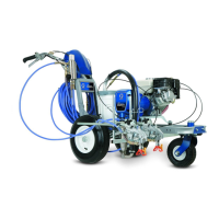
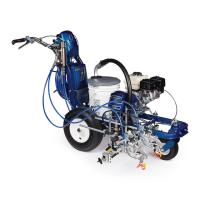
This document outlines the application methods for the Graco LineLazer™ V HP Auto Series with LazerGuide™ 2000, a professional-grade line striping system designed for outdoor use in parking lot layout applications. It is not intended for use in explosive atmospheres or hazardous locations.

Function Description:

The LineLazer V HP Auto Series with LazerGuide 2000 is an advanced system for precise and efficient line striping, particularly in parking lot layouts. It integrates laser guidance and an automated layout system to simplify the process of marking stalls, cross hatches, and center/lane lines. The system allows users to define start and finish reference points, calculate stall dimensions, and automatically lay down dots or continuous lines with high accuracy. The LazerGuide 1700 Start/Stop Laser and LazerGuide 2000 Laser work in conjunction to provide precise positioning and measurement. The LiveLook display serves as the central interface for controlling layout modes, calibration, and monitoring operational parameters.

Important Technical Specifications:

  • Maximum Operating Pressure: 3300 psi (22.8 MPa, 228 bar)
  • Calibration Course: Minimum 24 ft precision course required for accurate calibration.
  • Minimum Engine RPM for Placing Dots: 2600 RPM.
  • LazerGuide 1700 Start/Stop Laser: Used for establishing start/stop points and measuring distances.
  • LazerGuide 2000 Laser: Used in conjunction with a Target Box for alignment and maintaining straight lines.
  • Guns: Recommended setup involves GUN 1 on the right side and GUN 2 on the left side, positioned straight across from one another, slightly in front of the front tire.

Usage Features:

General Operation:

  • LiveLook Display: The primary interface for all layout modes, calibration, and settings.
  • Gun Trigger Control: Used to start and stop measuring, place reference dots, and apply paint.
  • Remote Switch: Used during calibration to move the LazerGuide 1700 Start/Stop Laser.
  • UP/DOWN Arrows: Used to adjust numerical values, such as the number of stalls or stall size.

Calibration:

  • A minimum 24 ft (maximum 100 ft) steel measuring tape is required.
  • The striper is aligned parallel to the tape measure with the LazerGuide 1700 Start/Stop Laser at the 1 ft mark.
  • The calibration distance is selected on the LiveLook display.
  • The LazerGuide 1700 Start/Stop Laser is moved along the tape measure to a point 1 ft beyond the inputted measurement (e.g., to 25 ft for a 24 ft calibration).
  • The LiveLook display measures in both forward and backward directions, allowing corrections if the finish point is overshot.
  • Verification of calibration is done in Measure Mode.
  • Calibration for LazerGuide 2000 is detailed in manual 3A5294 or the LazerGuide 2000 Setup & Calibration video.

Measure Mode:

  • Used for measuring and marking specific distances.
  • The LazerGuide 1700 Start/Stop Laser is placed on the START point, and the GUN TRIGGER CONTROL button is pressed.
  • The striper is moved in a straight line to the FINISH point, and the GUN TRIGGER CONTROL button is pressed again.
  • When an Auto gun is active, momentarily holding the GUN TRIGGER CONTROL applies a dot. Continuous dotted lines with 1 ft spacing are produced when moving while holding the button, useful for pre-marking.
  • The striper measures moving forward or in reverse.

Stall Calculator Offset:

  • This feature allows for an offset (x) value to be input in the STALL CALCULATOR screen.
  • This value is measured from the curb or START reference dot to the LazerGuide 1700 Start/Stop Laser under the spray gun.
  • The offset can be stored for future layout jobs by holding the D button for 2 seconds.

Basic Stall Layout (Layout Mode):

  • Establishing Reference Dots:
    • Select the desired stall depth (STALL SIZE) on the LiveLook display (e.g., 18 ft from the inside curb).
    • Activate Gun 1 or 2.
    • Align the LazerGuide 1700 Start/Stop Laser with the inside curb, press the GUN TRIGGER CONTROL to place the curb START reference dot.
    • Move the striper away from the curb until the second START reference dot is placed (e.g., 18 ft from the inside curb).
    • Press the GUN TRIGGER CONTROL to stop placing dots.
    • Repeat the process at the other end of the parking lot for FINISH reference dots.
    • Position the LazerGuide 2000 Target Box at the FINISH reference dot, facing the START reference dot.
  • Marking Dots at Beginning of Each Stall:
    • Move the striper back to the START point, aligning LazerGuide 1700 with the START reference dot and LazerGuide 2000 with the Target Box.
    • Press GUN TRIGGER CONTROL to start laying dots at the defined width (e.g., 9.03 ft).
    • Move the striper toward the FINISH reference dot, keeping LazerGuide 2000 aligned with the Target Box.
    • Press GUN TRIGGER CONTROL after the last FINISH reference dot to stop.

Basic Stall Layout (Stall Calculator):

  • Measuring for Automatic Calculation:
    • Move the striper to the START point, aligning LazerGuide 1700 with the START reference dot and LazerGuide 2000 with the Target Box.
    • Go to the STALL CALCULATOR screen, choose nominal stall width (e.g., 9 ft).
    • Press GUN TRIGGER CONTROL to start measuring.
    • Move the striper toward the FINISH reference dot, keeping LazerGuide 2000 aligned.
    • Press GUN TRIGGER CONTROL to stop measuring at the FINISH reference dot.
    • Use UP/DOWN arrows to adjust the number of desired stalls. The calculated STALL SIZE is automatically transferred to LAYOUT MODE.
  • Marking Dots Near the Curb:
    • Position the striper with LazerGuide 1700 at the curb and GUN 2 (left gun) on the START reference dot, facing the left curb.
    • Press GUN TRIGGER CONTROL and back up along the curb to make a second dot (e.g., at 9.03 ft).
    • Press GUN TRIGGER CONTROL to stop.
    • Rotate the striper 180 degrees, aligning LazerGuide 1700 over the newly laid reference dot.
    • Press GUN TRIGGER CONTROL to start laying dots at the defined width, moving toward the FINISH reference dot while following the curb.
    • Press GUN TRIGGER CONTROL after the last FINISH reference dot to stop.

Basic Stall Layout (Striping Mode):

  • Connect the laid dots with the striper, using the Target Box for guidance if needed.

Island Stall Layout (Layout Mode):

  • Establishing Reference Dots:
    • Define the CENTER of the cement island on both ends using MEASURE MODE or a tape measure.
    • Establish START and FINISH reference dots by measuring from the CENTER reference dot (e.g., 18 ft).
    • Set the LazerGuide 2000 Target Box at one FINISH reference dot, facing the corresponding START reference dot.
  • Placing Dots at Beginning and End of Each Stall Line:
    • Move the striper back to the START point, aligning LazerGuide 1700 with the START reference dot and LazerGuide 2000 with the Target Box.
    • Press GUN TRIGGER CONTROL to start laying dots at the defined width (e.g., 9.02 ft).
    • Move the striper toward the FINISH reference dot, keeping LazerGuide 2000 aligned.
    • Press GUN TRIGGER CONTROL after the last FINISH reference dot to stop.
    • Repeat for the other end of double stalls.

Island Stall Layout (Stall Calculator):

  • Measuring for Automatic Calculation:
    • Move the striper to the START point, aligning LazerGuide 1700 with the START reference dot and LazerGuide 2000 with the Target Box.
    • Go to the STALL CALCULATOR screen, choose nominal stall width (e.g., 9 ft).
    • Press GUN TRIGGER CONTROL to start measuring.
    • Move the striper toward the FINISH reference dot, keeping LazerGuide 2000 aligned.
    • Press GUN TRIGGER CONTROL to stop measuring at the FINISH reference dot.
    • Use UP/DOWN arrows to adjust the number of desired stalls. The calculated STALL SIZE is automatically transferred to LAYOUT MODE.

Island Stall Layout (Striping Mode):

  • Connect the dots with the striper, using the Target Box if needed.
  • Skip-Line Feature: For multiple aligned island stalls, mark the first START and final FINISH reference dots. Use the skip-line feature on the LiveLook display to save time (e.g., 36 ft line/24 ft skip for 18 ft deep stalls and a 24 ft drive path).

Radius Stall Layout (Layout Mode):

  • Establishing Perimeter Reference Line:
    • Select stall depth (STALL SIZE) on LiveLook display (e.g., 18 ft from inside curb).
    • Activate Gun 1 or 2.
    • Align LazerGuide 1700 with the inside curb, press GUN TRIGGER CONTROL for the curb START reference dot.
    • Move striper away from curb until the outer radius reference dot is placed (e.g., 18 ft from inside curb).
    • Press GUN TRIGGER CONTROL to stop placing dots.
    • Repeat to define a sufficient reference line for stall starts.
  • Marking Dots at End of Each Stall:
    • Position striper with LazerGuide 1700 at the curb and GUN 2 on the START reference dot, facing the left curb.
    • Press GUN TRIGGER CONTROL and back up along the bottom curb to make a second dot (e.g., at 9.03 ft).
    • Press GUN TRIGGER CONTROL to stop.
    • Rotate striper 180 degrees, aligning LazerGuide 1700 over the newly laid reference dot.
    • Press GUN TRIGGER CONTROL to start laying dots at the defined width, moving toward the FINISH reference dot while following the curb.
    • Press GUN TRIGGER CONTROL after the last FINISH reference dot to stop.

Radius Stall Layout (Stall Calculator):

  • Measure Inner Radius Distance:
    • Move striper to START point at inner curb, align LazerGuide 1700 with START point. (Use STALL CALCULATOR OFFSET if curb prevents alignment).
    • Go to STALL CALCULATOR screen, select nominal stall width (e.g., 9 ft).
    • Press GUN TRIGGER CONTROL to start measuring.
    • Move striper toward FINISH point, following inner curb with LazerGuide 1700.
    • Press GUN TRIGGER CONTROL to stop measuring at FINISH point.
    • Use UP/DOWN arrows to adjust the number of stalls to match the inner curb radius measurement. Calculated STALL SIZE is transferred to LAYOUT MODE.
  • Measure Outer Perimeter Distance:
    • Move striper to START point of stalls (e.g., 18 ft from inner curb), align LazerGuide 1700 with START point.
    • Go to STALL CALCULATOR screen, press GUN TRIGGER CONTROL to start measuring.
    • Move striper toward FINISH point, following the previously created reference line with LazerGuide 1700.
    • Press GUN TRIGGER CONTROL to stop measuring at FINISH point.
    • Use UP/DOWN arrows to adjust the number of stalls to match the inner curb radius measurement. Calculated STALL SIZE is transferred to LAYOUT MODE.

Radius Stall Layout (Striping Mode):

  • Connect the dots with the striper, using the Target Box if needed.

Angle Stall Layout (Parking Mode):

  • START/FINISH Reference Dots:
    • Define the CENTER of the cement island on both ends using MEASURE MODE or a tape measure.
    • Establish START and FINISH reference dots by measuring from the CENTER reference dot (e.g., 18 ft).
    • Set the LazerGuide 2000 Target Box at one FINISH reference dot, facing the corresponding START reference dot.

Angle Stall Layout (Angle Calculation):

  • Set up LiveLook Display:
    • Go to LAYOUT MODE - ANGLE CALC on LiveLook display.
    • Adjust desired ANGLE, STALL DEPTH, and STALL SIZE. The system automatically calculates "offset" and "dot spacing."
    • Press B to transfer "dot spacing" to LAYOUT MODE.
    • Press C to transfer "offset distance" to LAYOUT MODE. (No numbers are transferred if E is pressed).

Angle Stall Layout (Layout Mode):

  • Mark Dots at End of Each Stall:
    • Move striper to one START point, align LazerGuide 1700 with START reference dot and LazerGuide 2000 with Target Box.
    • Press GUN TRIGGER CONTROL to start laying dots.
    • Move striper toward FINISH reference dot, keeping LazerGuide 2000 aligned.
    • Press GUN TRIGGER CONTROL after the last FINISH reference dot to stop.
    • Move Target Box to the second FINISH point and striper to the second START point; repeat steps.

Angle Stall Layout (Striping Mode):

  • Connect the dots with the striper, using the Target Box if needed.

Cross Hatch Layout (Layout Mode):

  • Establish Boundary and Apply Dots:
    • Set gun to active. Press GUN TRIGGER CONTROL to mark START and FINISH dots.
    • Adjust STALL SIZE to achieve desired cross hatch spacing.
    • Place dots around the perimeter of the area.

Cross Hatch Layout (Striping Mode):

  • Connect the dots with the striper, using the Target Box if needed.
  • Paint the interior by connecting the dots. If ends are rounded, establish this before painting.
  • Paint the perimeter.

Marker Mode Layout (Center Lines and Lane Lines Mode):

  • Paint Lines (Connect the Dots):
    • Automatic marker layout example shows typical lane line layout for reflective markers.
    • Set space sizes up to 8 consecutive measurements.
    • Leaving zeros in any space will cause AutoLayout to skip to the next measurement in a continuous loop.
  • Other Uses: Multiple spaced handicap stall layout, double line stalls.

Maintenance Features:

  • The manual emphasizes reading all warnings and instructions in this manual and related manuals.
  • Users should be familiar with the controls and proper usage of the equipment.
  • Instructions should be saved for future reference.
  • Graco provides a standard warranty covering defects in material and workmanship for twelve months from the date of sale, provided the equipment is installed, operated, and maintained according to Graco's recommendations.
  • The warranty does not cover normal wear and tear, faulty installation, misapplication, abrasion, corrosion, improper maintenance, negligence, accident, tampering, or use of non-Graco components.
  • The warranty is conditioned on the prepaid return of defective equipment to an authorized Graco distributor for verification. Repaired or replaced parts are returned prepaid. If no defect is found, repairs are charged.
  • Graco disclaims other warranties, express or implied, including merchantability or fitness for a particular purpose.
  • Graco is not liable for indirect, incidental, special, or consequential damages.
  • Actions for breach of warranty must be brought within two years of the sale date.
  • Graco makes no warranty for accessories, equipment, materials, or components not manufactured by Graco; these are subject to their manufacturer's warranty.

Graco LineLazer V HP Auto Series Specifications

General IconGeneral
BrandGraco
ModelLineLazer V HP Auto Series
CategoryConstruction Equipment
LanguageEnglish

Related product manuals