308685 33
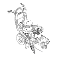
Reassembly
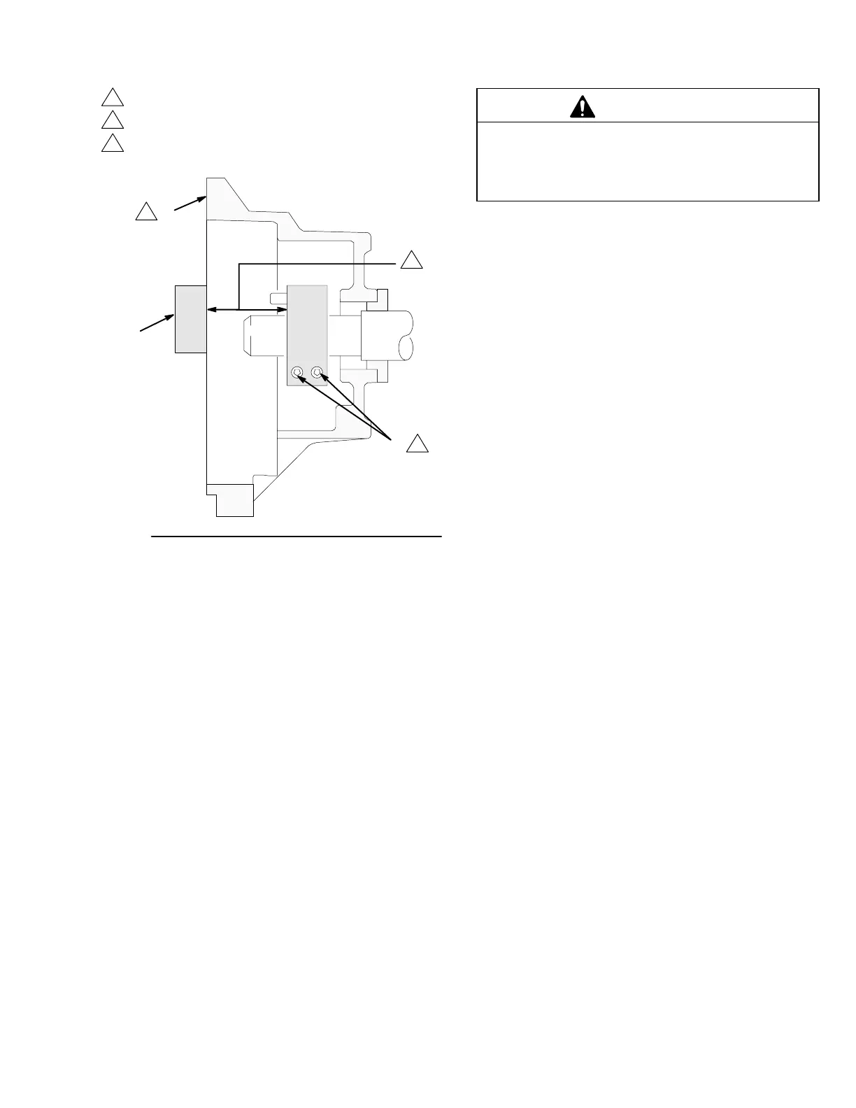
Fig. 24
56
1
B
1
3
2
The face of the housing.
1.41 ".010 inch (35.8 ".25 mm).
Torque the screws to
120 in–lb (14 N.m).
1
2
3
05078
CAUTION
The sprayer will be out of balance when only the
engine and clutch housing are installed. Support the
rear of the cart to prevent the sprayer from falling
over.
5. Place the engine (59) and drive assembly on the
mounting plate. Align the mounting holes. Carefully
guide the engine wire and wiring harness (E) from
the field, through the appropriate grommets (24) in
the mounting plate (A). Install the flange screws
(71) and locknuts (46). Install the screw (20), lock
washer (73), and washer (21). Tighten all three
screws. Connect the engine wire to the red wire
(B), and connect the black and white wires as
shown in the Detail drawing in Fig. 19. Place the
engine and drive assembly and mounting plate on
the cart. Install the four mounting plate screws (x),
washers (Y), and nuts (Z).