Models
2 311238G
Contents
Models . . . . . . . . . . . . . . . . . . . . . . . . . . . . . . . . . . . 2
Air Motor Part No. Matrix . . . . . . . . . . . . . . . . . . . 2
Air Motor Part Nos. . . . . . . . . . . . . . . . . . . . . . . . 3
Warnings . . . . . . . . . . . . . . . . . . . . . . . . . . . . . . . . . 4
Component Identification . . . . . . . . . . . . . . . . . . . . 6
De-icing Control (F) . . . . . . . . . . . . . . . . . . . . . . . 7
Integrated Air Control Module Accessory . . . . . . 7
Grounding . . . . . . . . . . . . . . . . . . . . . . . . . . . . . . . . 7
DataTrak Controls and Indicators . . . . . . . . . . . . . 8
DataTrak Operation . . . . . . . . . . . . . . . . . . . . . . . . . 9
Setup Mode . . . . . . . . . . . . . . . . . . . . . . . . . . . . . 9
Run Mode . . . . . . . . . . . . . . . . . . . . . . . . . . . . . . 9
Replace the DataTrak Module Battery or Fuse . 12
Troubleshooting . . . . . . . . . . . . . . . . . . . . . . . . . . . 14
Repair . . . . . . . . . . . . . . . . . . . . . . . . . . . . . . . . . . . 16
Preventive Maintenance Schedule . . . . . . . . . . 16
Tools Required . . . . . . . . . . . . . . . . . . . . . . . . . 16
Pressure Relief Procedure . . . . . . . . . . . . . . . . 16
Air Valve Repair . . . . . . . . . . . . . . . . . . . . . . . . 16
Cylinder and Piston Repair . . . . . . . . . . . . . . . . 20
Poppet Repair . . . . . . . . . . . . . . . . . . . . . . . . . . 22
Replace the Linear Sensor (if present) . . . . . . . 23
Parts . . . . . . . . . . . . . . . . . . . . . . . . . . . . . . . . . . . . 24
Air Motor Parts Drawing
(Shown with DataTrak and Low Noise Exhaust)
24
Air Motor Parts Drawing (Shown with Linear Sensor)
25
NXT Model 2200 Air Motors . . . . . . . . . . . . . . . 26
NXT Model 3400 Air Motors . . . . . . . . . . . . . . . 27
NXT Model 6500 Air Motors . . . . . . . . . . . . . . . 28
Air Valve . . . . . . . . . . . . . . . . . . . . . . . . . . . . . . 30
Dimensions . . . . . . . . . . . . . . . . . . . . . . . . . . . . . . . 32
Accessories . . . . . . . . . . . . . . . . . . . . . . . . . . . . . . 32
Mounting Hole Diagrams . . . . . . . . . . . . . . . . . . . . 33
Technical Data . . . . . . . . . . . . . . . . . . . . . . . . . . . . 34
Graco Standard Warranty . . . . . . . . . . . . . . . . . . . 38
Graco Information . . . . . . . . . . . . . . . . . . . . . . . . . 38
Models
Air Motor Part No. Matrix
Check your motor’s identification plate (ID) for the 6-digit part number of your motor. Use the
following matrix to define the construction of your motor, based on the six digits. For exam-
ple, Motor Part No. N65DT0 represents an NXT motor (N), 6500 cc per stroke (6 5), with
de-icing exhaust (D) and DataTrak monitoring (T). The last digit (0) is unassigned.
ID
N6 5 D T0
First Digit
(Motor)
Second and Third Digits
(motor size in cc per stroke)
Fourth Digit
(Exhaust Type)
Fifth Digit
(Data Monitoring)
Sixth Digit
(unassigned)
N (NXT
Air Motor)
65 6500 D De-icing N None 0 None
assigned
34 3400 L Low noise T DataTrak
22 2200 R Remote (see note below) H Linear Sensor
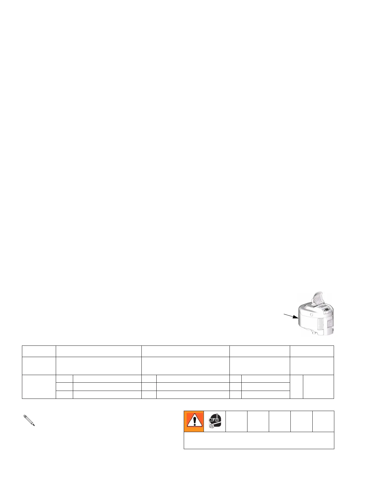
Remote exhaust models have a 1 in. npt(f) exhaust
outlet, allowing installation of a muffler or plumbing
to route exhaust to a remote location.
Do not operate the remote exhaust air motor without a
plumbed exhaust line or muffler installed.