Setup
Connect Connect
Connect
Power Power
Power
Allelectricalwiringmustbedonebyaqualied
electricianandcomplywithalllocalcodesand
regulations.
1.Turnmainpowerswitch(MP)OFF.
2.Openelectricalenclosuredoor.
NOTE: NOTE:
NOTE:
Terminaljumpersarelocatedinsidethe
electricalenclosuredoorifequipped.
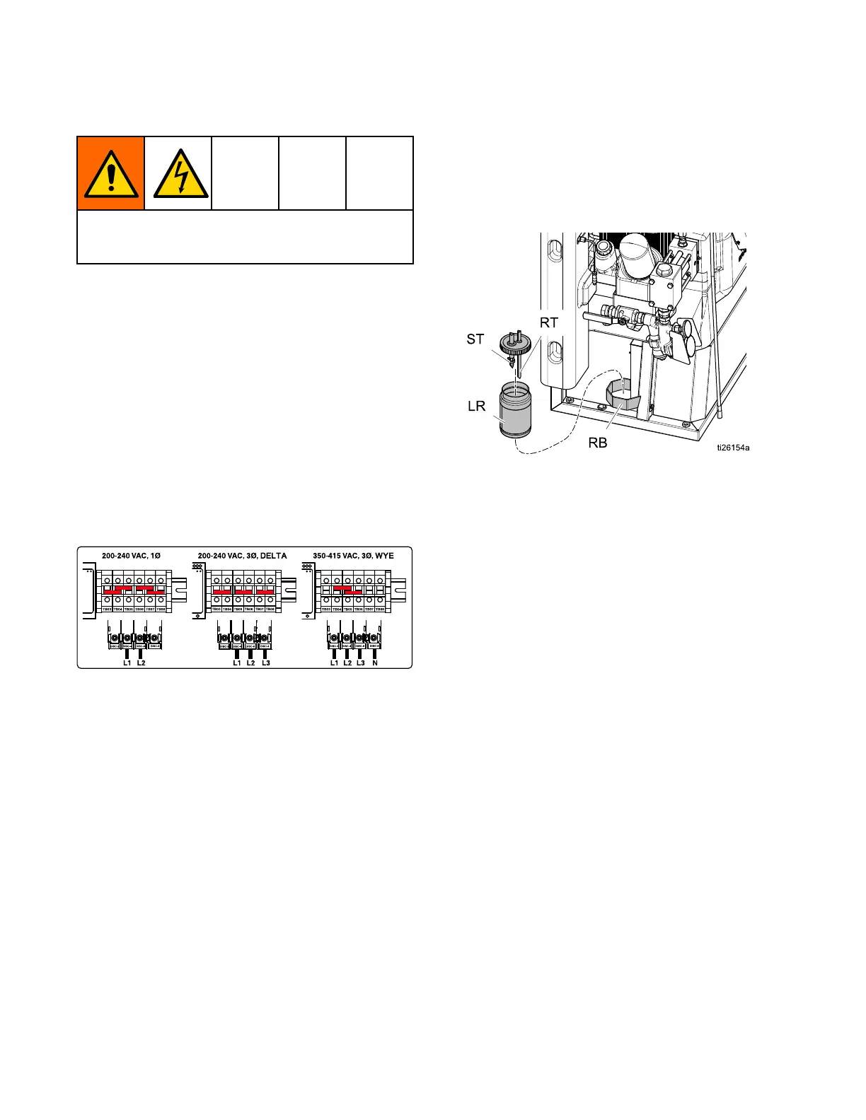
3.Installsuppliedterminaljumpersinthepositions
showninimageforthepowersourceused(H-30
andH-XP2modelsonly).
4.Routepowercablethroughstrainrelief(EC)in
electricalenclosure.
5.Connectincomingpowerwiresasshownin
image.Gentlypullonallconnectionstoverify
theyareproperlysecured.
6.Verifyallitemsareconnectedproperlyasshown
inimagethencloseelectricalenclosuredoor.
SeeModels,page9forReactorpower
requirements.
NOTE: NOTE:
NOTE:
350–415VACsystemsarenotdesignedto
operatefrom480VACpowersource.
Lubrication Lubrication
Lubrication
System System
System
Setup Setup
Setup
Component Component
Component
A A
A
(ISO) (ISO)
(ISO)
Pump: Pump:
Pump:
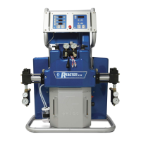
FillISOlubereservoir
(LR)withGracoThroatSealLiquid(TSL),part
206995(supplied).
1.Liftthelubricantreservoir(LR)outofthebracket
(RB)andremovethecontainerfromthecap.
2.Fillwithfreshlubricant.Threadthereservoironto
thecapassemblyandplaceitinthebracket(RB).
3.Pushthelargerdiametersupplytube(ST)
approximately1/3ofthewayintothereservoir.
4.Pushthesmallerdiameterreturntube(RT)into
thereservoiruntilitreachesthebottom.
NOTE: NOTE:
NOTE:
Thereturn(RT)mustreachthebottomof
thereservoirtoensurethatisocyanatecrystals
willsettletothebottomandnotbesiphonedinto
thesupplytube(ST)andreturnedtothepump.
5.Thelubricationisreadyforoperation.Nopriming
isrequired.
32 334945J
 Loading...