Repair
311512A 21
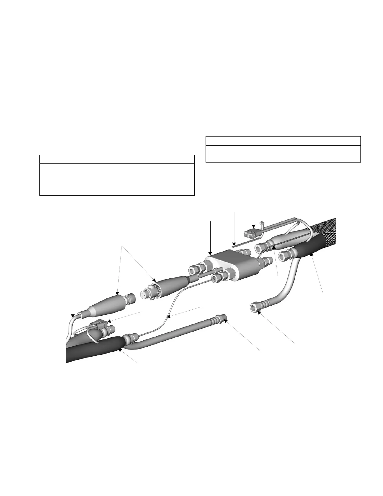
Removal
1. Disconnect air hoses (C, L) and electrical connec-
tors.
2. Disconnect FTS from whip hose and fluid hoses.
3. Remove ground wire (MM) from ground screw on
underside of FTS.
4. Remove FTS probe (UU) from component A (ISO)
side of hose.
Installation
1. Carefully extend FTS probe (UU). Do not bend or
kink probe. Insert in component A (ISO) side of
main hose.
2. Connect whip hose ground wire (MM) to ground
screw on underside of FTS.
3. Install FTS in reverse order of removal. Leave slack
in cables as stress relief, to prevent cable failure.
4. Secure power connector (NN) with wire tie (PP) to
prevent it from pulling apart.
5. Secure hose and cable connection with tape and
install protective covering.
F
IG. 1: Fluid Temperature Sensor and Heated Hoses
CAUTION
To prevent damage to probe, do not kink or exces-
sively bend whip hose. Do not coil hose tighter than
the minimum bend radius of 3 ft (0.9 m). Do not sub-
ject hose to excessive weight, impact, or other abuse.
CAUTION
It is important to secure power connectors with wire
ties (PP) so that they do not pull apart.
PP
ti2684a1
KK
LL
MM
RR
QQ
UU
NN
HH
SS
TT

 Loading...


