Repair
30 309574C
Transducers
2. Relieve pressure, page 8.
3. Refer to electrical diagrams. Motor control board is
on right side inside cabinet.
4. Disconnect transducer cable at board; transducer A
from J3, transducer B from J8. Swap connections
and check if diagnostic code follows, page 12.
5. If transducer fails test, thread cable through top of
cabinet. Note path as cable must be replaced in
same way.
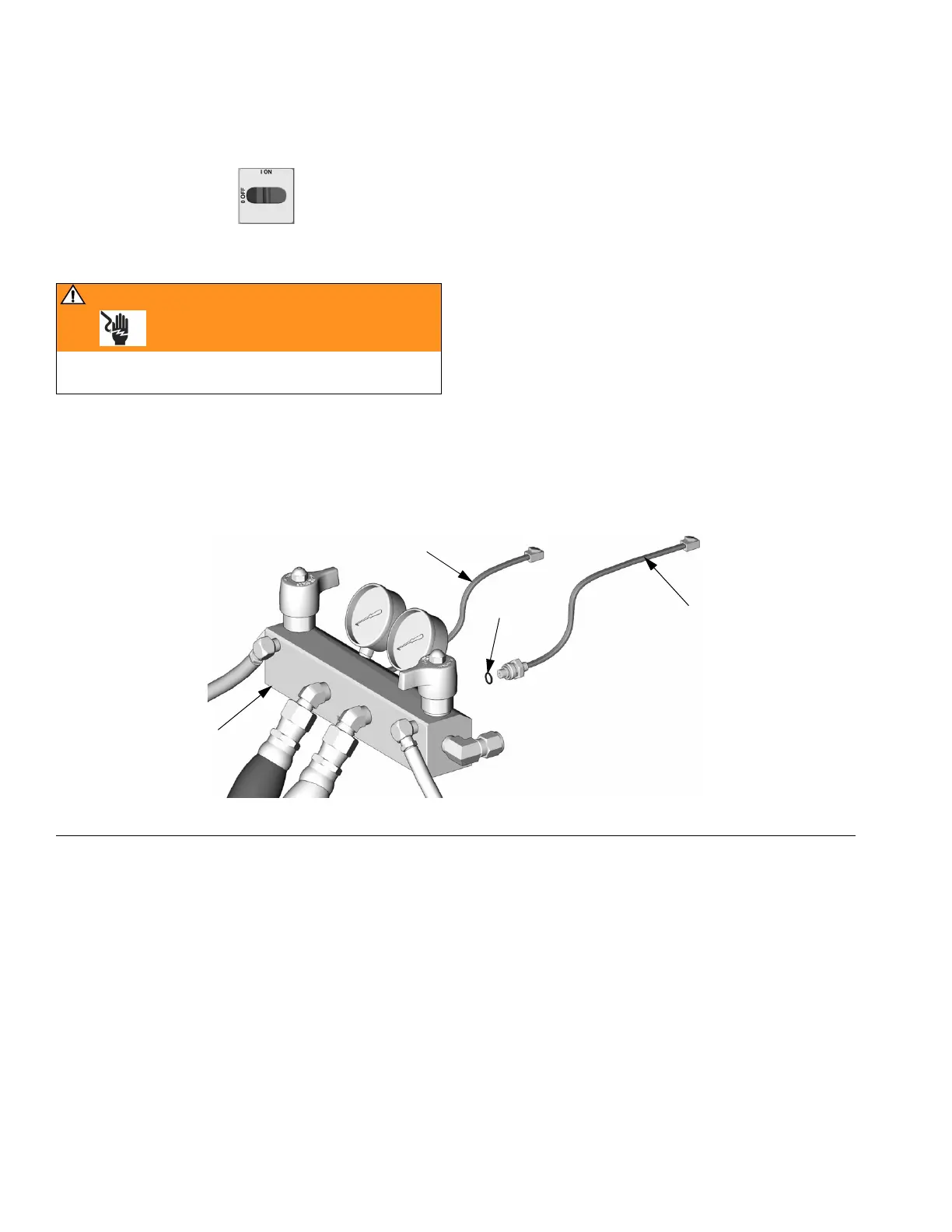
6. Install o-ring (720) on new transducer (706), F
IG
. 8.
7. Install transducer in manifold. Mark end of cable
with tape (red=transducer A, blue=transducer B).
8. Route cable into cabinet and thread into bundle as
before.
9. Connect transducer cable at board; transducer A
(red) to J3, transducer B (blue) to J8.
1. Turn main power OFF . Disconnect power
supply.
WARNING
Read warnings, page 5. Wait 5 min for stored voltage
to discharge (E-30 and E-XP2 models only).
F
IG
. 8. Transducers
TI3169a
720
706 (B Side)
701
706 (A Side)