18
308-799
Motor
Brush Replacement
NOTE: Replace
brushes worn to
less than 1/2 in. Note
that
brushes wear dif
ferently on each side of mo
-
tor, so check both. Brush Repair Kit 220–853 is
available. A new spring clip, 1 10–816, may be
purchased
separately
.
WARNING
INJECTION HAZARD
T
o reduce the risk of serious injury
,
whenever you are instructed to relieve
pressure, follow the
Pressure Relief
Procedure
on page 7.
NOTE: Read
General Repair
Information on page 16
before
doing this procedure.
1.
Relieve pressure.
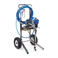
2.
Remove motor shield (54). Remove inspection
covers (B) and gaskets on each side of motor
.
See Fig. 1
1.
B
54
Fig. 11
7703A
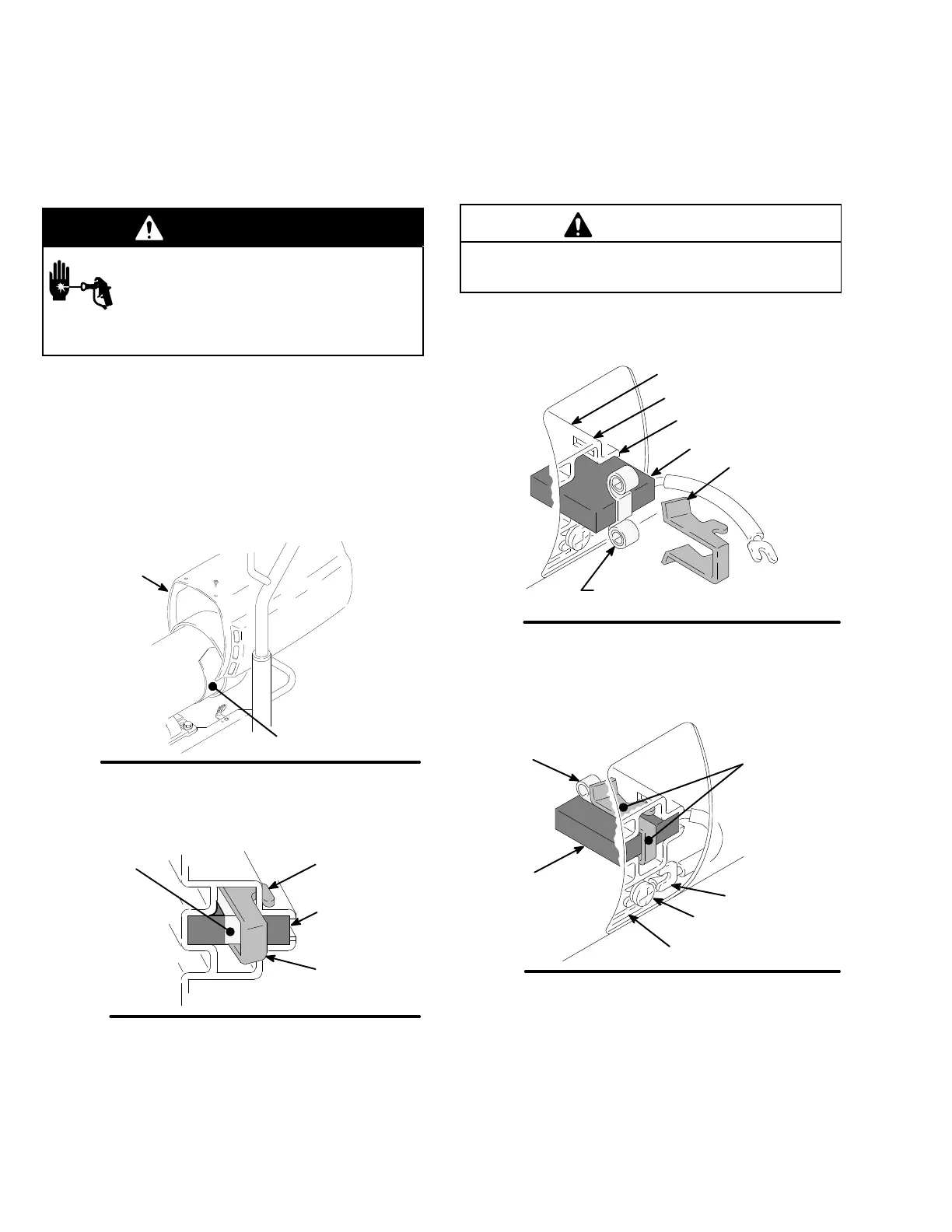
3.
Push in spring clip to release hooks from brush
holder
. Pull out spring clip. See Fig. 12.
Fig. 12
SPRING
CLIP
110–816
HOOK
SPRING
01227
BRUSH
4. Loosen
brush lead terminal screw
. Pull brush lead
away
, leaving motor lead terminal in place. Re
-
move brush and spring. See Fig. 14.
5.
Inspect commutator for excessive pitting, burning
or gouging. A black color on commutator is normal.
Have commutator resurfaced by a qualified motor
repair shop if brushes seem to wear too fast.
CAUTION
When installing the brushes, follow all steps carefully
to avoid damaging the parts.
6.
Install new brush so lead is in long slot of holder
.
See Fig. 13.
Fig. 13
BRUSH
SHORT
SLOT
LONG SLOT
BRUSH HOLDER
NOTE: SPRING MUST COIL
IN THIS DIRECTION
SPRING
CLIP
01227
7. Slide
terminal under terminal screw washer and
tighten screw. Be sure motor lead is still connected
at screw. See Fig. 14.
Fig. 14
SPRING
BRUSH
LEAD
TERMINAL SCREW
MOT
OR LEAD
TERMINAL
BRUSH
SPRING CLIP
01227
8. Place
spring on brush as shown in Fig. 13.
9.
Install spring clip and push it down to hook short
slots in housing. See Fig. 13.
10.
Repeat for other side.
 Loading...