308852 11
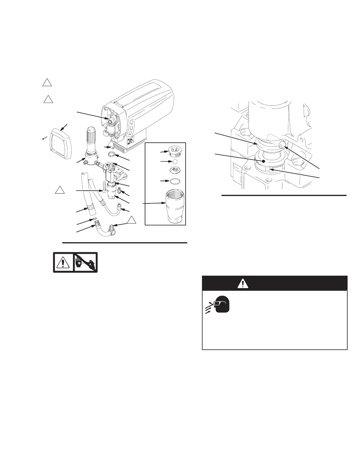
Displacement Pump
NOTE: Packing Repair Kit 235703 is available. Refer-
ence numbers of parts included in the kit are marked
with an asterisk, i.e., (223*).
Removing pump (See Fig.8)
47
7736
213
*227
*214
215
222
15
14
17
18
50
36
43
45
11
Fig. 8
Apply pipe
sealant (110110)
48
Torque to
50 ft-lb (68 Nm)
Models 232135, 232137
12
1.
Relieve pressure; page 3.
2. Flush pump, if possible. Relieve pressure. Stop
pump with piston rod (222) in its lowest position, if
possible. To lower piston rod manually, rotate
motor fan blades.
3. Remove filter (48).
4. Models 232135, 232137. While pulling upward on
suction hose (47), unscrew hose from inlet tube
(43). Unscrew drain hose (50) from displacement
pump nipple (36).
5. Models 232138, 232136. Remove suction tube
(43). Unscrew drain tube (84) from displacement
pump nipple (36).
6. Use a screwdriver to push retaining spring (15) up
and push out pin (14).
7. Loosen screws (17). Remove pump (18).
Repairing pump
See manual 308815 for displacement pump repair
instructions and parts.
Installing pump (See Fig. 8 and 9)
14
201
15
Fig. 9
202
7840A
1. Lightly grease or oil transducer (67). See Fig. 15.
Guide pump over alignment pins and pressure
transducer. Tap it into position with a soft hammer.
Tighten screws (17) to 50 ft-lb (68 Nm).
2. Align hole in rod (222) with connecting rod assem-
bly (12). Use screwdriver to push retaining spring
(15) up and push in pin (14). Push retaining spring
into place around connecting rod.
WARNING
MOVING PARTS HAZARD
Be sure retaining spring (18) is firmly in
groove all around, to prevent pin (14)
from working loose.
See Fig. 9.
If pin works loose, parts (including pump connect-
ing rod or bearing housing) could project into the air
and cause serious injury or property damage.
3. Replace o-ring (45) if worn or damaged. See page
17. Reconnect suction and drain hoses (47, 50).
Install front cover (11).
4. Tighten packing nut (202) enough to stop leakage,
but no tighter. Fill packing nut full with Graco TSL.
Push plug (201) into packing nut.

 Loading...