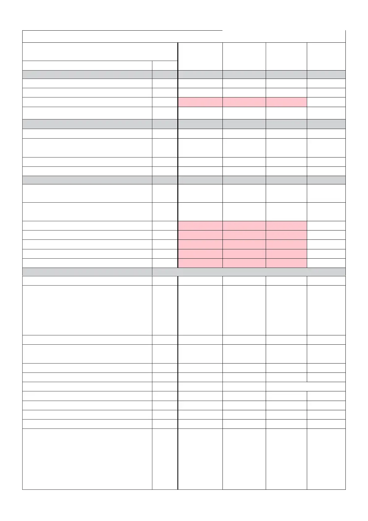
Appendix I Gram factory settings for AKCC550A (U/KG/FG cabinets)
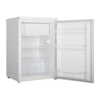
Gram default
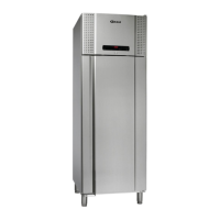
settings U models
(Solid door)
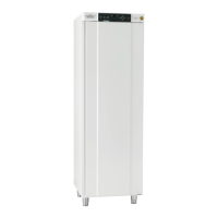
Gram default
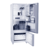
settings KG models
(Glass door)
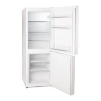
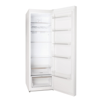
Gram default
settings MIDI FG
models (Glass
door)
X = Parameters
to be
considered/set
by installer
Injection control function
Max. value of superheat reference
Min. value of superheat reference
MOP temperature. Off if MOP temp. = 15.0 °C
Period time of AKV pulsation
Only for trained personnel
Fan stop temperature (S5)
Pulse operation on fans: 0=No pulse operation, 1=At
thermostat cuts out only, 2= Only at thermostat cut outs
during night operation
Period time for fan pulsation (on-time + off-time)
On-time in % of period time
Six start times for defrost. Setting of hours.
0=OFF
Six start times for defrost. Setting of minutes.
0=OFF
Clock - Setting of minute
Delay of output signals after start-up
Input signal on DI1. Function:
0=not used. 1=status on DI1. 2=door function with alarm
when open. 3=door alarm when open. 4=defrost start (pulse-
signal). 5=ext.main switch. 6=night operation 7=thermostat
band changeover (activate r21). 8=alarm function when
closed. 9=alarm function when open.
10=case cleaning (pulse signal). 11=forced cooling at hot
gas defrost, 12=night cover. 15=case shut down
Network address (0 = off)
On/Off switch (Service Pin message) IMPORTANT! o61 must
be set prior to o04
(used at LON 485 and DANBUSS only)
Access code 1 (all settings)
Used sensor type: 0=Pt1000, 1=Ptc1000,
Read out of software version
Max hold time after coordinated defrost
Select signal for display view. S4% (100%=S4, 0%=S3)
Pressure transmitter working range – min. value
Pressure transmitter working range – max. value
Refrigerant setting:
3=R134a. 5=R717. 13=User defined. 14=R32. 15=R227.
16=R401A. 17=R507. 18=R402A. 19=R404A. 20=R407C.
21=R407A. 22=R407B. 23=R410A. 24=R170. 25=R290.
26=R600. 27=R600a. 28=R744. 29=R1270. 30=R417A.
31=R422A. 32=R413A. 33=R422D. 34=R427A.
35=R438A.36=XP10. 37=R407F. 38=R1234ze. 39=R1234yf.
40=R448A. 41=R449A. 42=R452A