Page 10
Fire Bowls and Inserts Premium Line
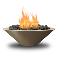
Automated Operation
(TYPICALLY MOUNTED WITH
POOL EQUIPMENT UP TO 150 FEET
AWAY FROM BURNER)
GAS INLET
GAS
OUTLET
12 VAC & CONDUIT (UNDERGROUND)
3/4” GAS PIPING (UNDERGROUND)
COMMERCIAL SAFETY PIPE TRAIN
SUPPLIED BY GRAND EFFECTS
(INSTALL AS CLOSE AS POSSIBLE
TO FIRE PIT)
120 VAC 60HZ INPUT
TO CONTROL PANEL
MANUAL GAS
VALVE
JUNCTION BOX
12 VAC
12 VAC
GAS OUTLET
12 VAC & CONDUIT (UNDERGROUND)
BOWL #1
BOWL #2
3/4” GAS PIPING (UNDERGROUND)
KEYED SWITCH
KILL SWITCH
12 VAC 60 HZ INPUT DETAILS
Figure 5. Commercial Installation
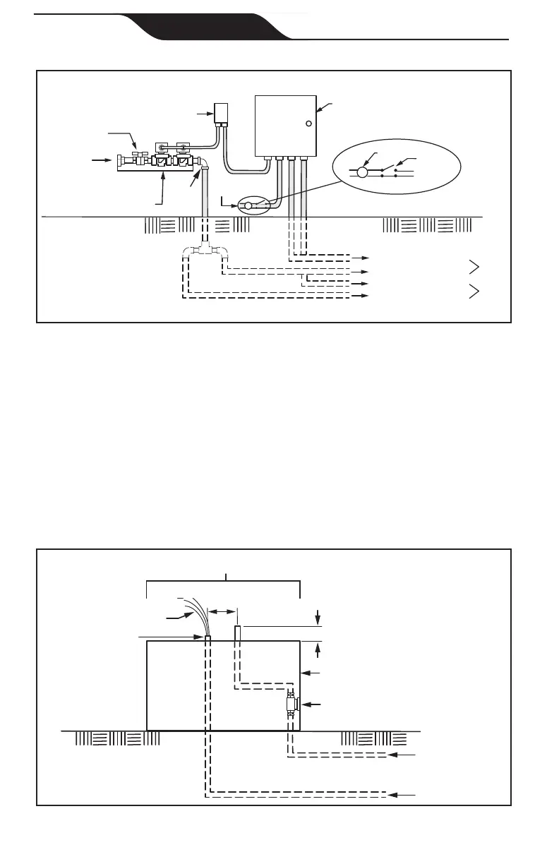
3. The piping must be reduced to ½″ NPT or larger at each bowl, as
shown in Figure 6.
4. At each bowl, install a 90° gas pipe elbow on the gas line for proper
installation of a gas hose. Do not kink or make a tight radius bend on
the gas hose.
Note: The gas and electrical connection at each bowl must be located
at the center of each bowl. The connections must be installed as
shown in Figure 7.
3/4” GAS PIPING
(UNDERGROUND)
12 VAC ELECTRICAL
(UNDERGROUND)
+
G
2-3/4”
MAX.
APPROX. 8-10”
WIRE LENGTH
1-1/2” MAX.
1” MIN.
1/2” KEY VALVE
WALL OR
PILASTER
PLUG OR CAP TO
KEEP WATER OUT
GAS AND ELECTRICAL
CENTERED IN COLUMN
Figure 6. Piping