INSTALLATION INSTRUCTIONS Gas Furnace: WFAR
440 01 7104 02 13
Specifications subject to change without notice.
CONDENSATE TRAP
Condensate Trap -- Upflow Orientation
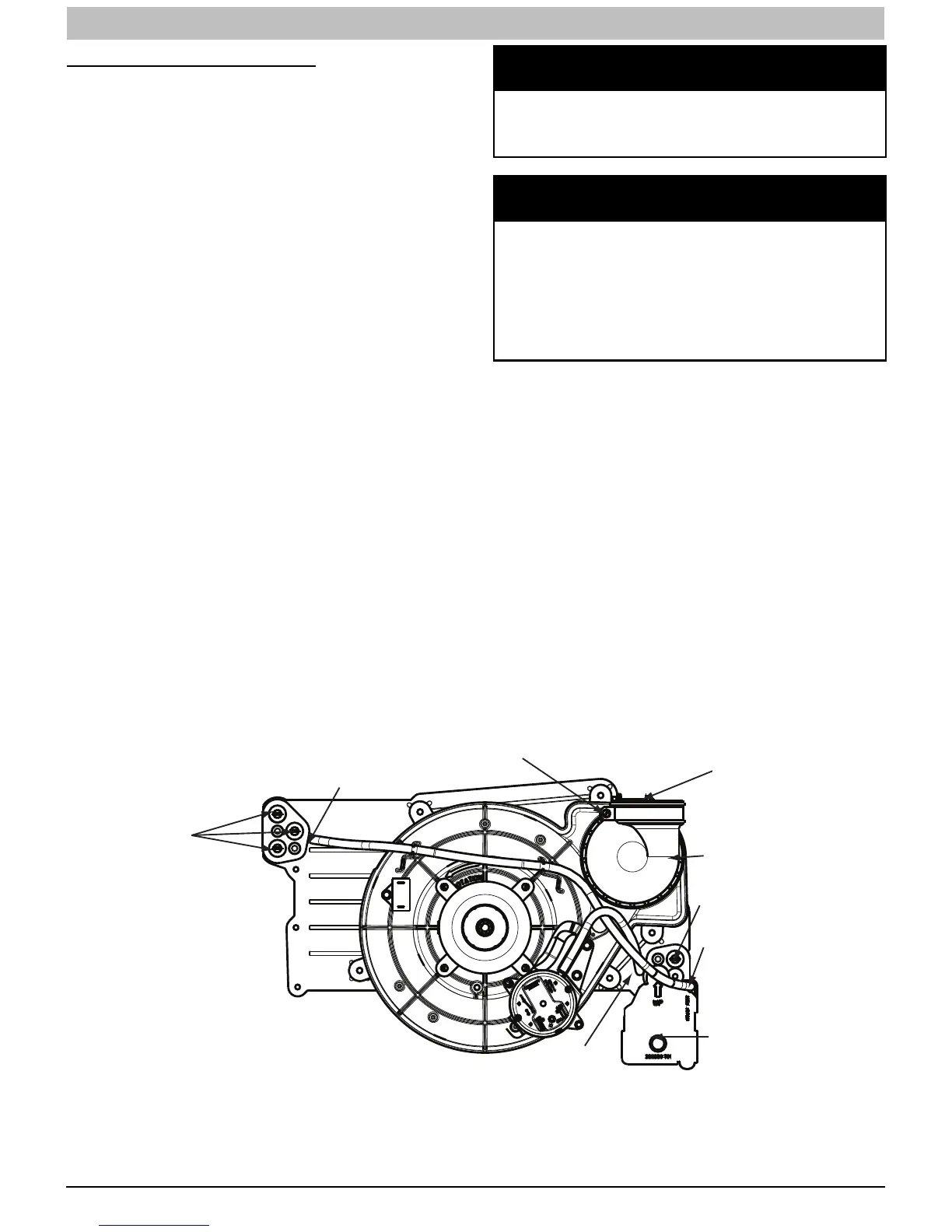
When the furnace is installed in the upflow position, it is not
necessary to relocate the condensate trap or associated
tubing. Refer to Figure 8 for upflow condensate trap
information. Refer to Condensate Drain section for information
how to install the condensate drain.
Condensate Trap -- Downflow
Orientation.
When the furnace is installed in the downflow position, the
condensate trap will be initially located at the upper left corner
of the collector box, as received from the factory. See the top
image in Figure 9. When the furnace is installed in the
downflow orientation, the condensate trap must be relocated
for proper condensate drainage. See the bottom image in
Figure 9.
To Relocate the Condensate Trap:
S Orient the furnace in the downflow position.
S Figure 9 shows the condensate trap and tubing before
and after relocation. Refer to Figure 9 to begin the
trap conversion.
S Refer to Condensate Drain section for information how
to install the condensate drain.
Condensate Trap -- Horizontal
Orientation.
When the furnace is installed in the horizontal right position, the
condensate trap will be initially located at the bottom of the
collector box, as received from the factory. See the top image in
Figure 10. When the furnace is installed in the horizontal left
position, the condensate trap will be initially located at the top of
the collector box, as received from the factory. See the top image
in Figure 11. In both cases, the trap must be repositioned on the
collector box for proper condensate drainage. See bottom images
in Figure 10 and Figure 11.
A field--supplied, accessory Horizontal Installation Kit (trap
grommet) is required for all direct--vent horizontal installations
(only). The kit contains a rubber casing grommet designed to seal
between the furnace casing and the condensate trap. (See
Figure 17.)
NOTICE
The field-supplied, accessory horizontal drain trap grommet
is ONLY REQUIRED FOR DIRECT VENT APPLICATIONS. It
is NOT required for applications using single-pipe or ventil-
ated combustion air venting.
NOTICE
The condensate trap extends below the side of the
casing in the horizontal position. A minimum of 2-in.
(51 mm) of clearance is required between the casing
side and the furnace platform for the trap to extend out
of the casing in the horizontal position. Allow at least
1/4-in. per foot (20mm per meter) of slope down and
away from the furnace in horizontal sections of drain
line.
To Relocate the Condensate Trap:
S Remove the knockout in the casing for the
condensate trap.
S Install the grommet in the casing when required for
direct--vent horizontal applications.
S Orient the furnace in the desired position.
S Allow for 2 in. (51 mm) of clearance underneath the
furnace for the condensate trap and drain line.
S Figure 10 shows the condensate trap and tubing
before and after relocation in the horizontal right
position.
S Figure 11 shows the condensate trap and tubing
before and after relocation in the horizontal left
position.
S Refer to the appropriate figure to begin the trap
conversion.
S Refer to Condensate Drain section for information how
to install the condensate drain.
Condensate Trap
Relief Port
Collector Box
Plugs
Pressure Switch
Port
Condensate Trap
Outlet
Condensate Trap
Relief Port
Collector Box
Plug
Vent Elbow
Vent Elbow Clamp
Vent Pipe Clamp
UPFLOW TRAP CONFIGURATION
1 & 2 Stage Units
A11307
Figure 8 -- Upflow Trap Configuration
(Appearance may vary)