INSTALLATION INSTRUCTIONS Gas Furnace: WFAR
440 01 7104 02 31
Specifications subject to change without notice.
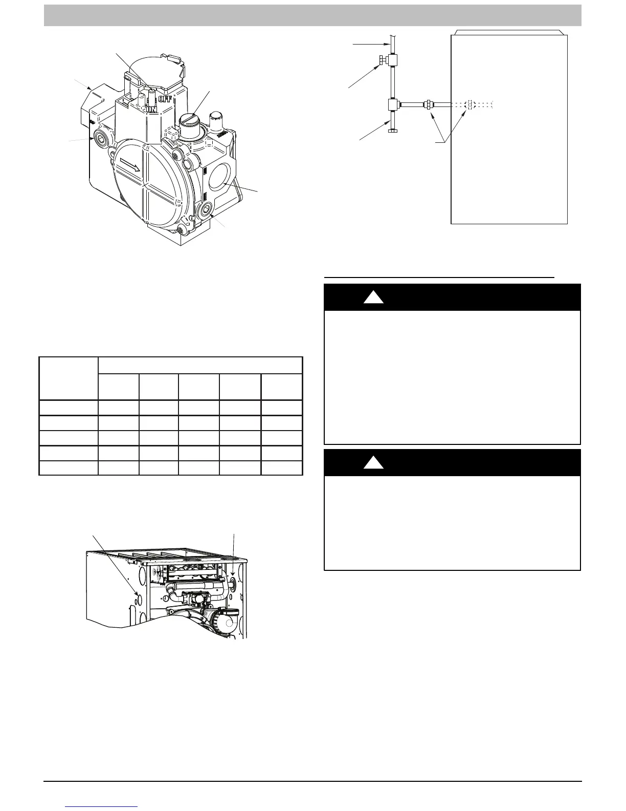
ON/OFF Switch
Regulator Seal Cap
Regulator Adjustment
Regulator Seal Cap under Cap
1/2” NPT Outlet
1/8” NPT Manifold
Pressure Tap
1/8” NPT Inlet
Pressure Tap
1/2” NPT Inlet
SINGLE-STAGE
A11153
Figure 31 -- Gas Valve
Gas Pipe Grommet
For direct vent (2-pipe) applications, the knockout for the gas
pipe must be sealed to prevent air leakage. Remove the
knockout, install the grommet in the knockout, then insert the
gas pipe. The grommet is included in the loose parts bag. See
Figure 32.
Table9–MaximumCapacityofPipe
NOMINAL
IRON
PIPE SIZE
IN. (MM)
LENGTH OF PIPE -- FT (M)
10
(3.0)
20
(6.0)
30
(9.1)
40
(12.1)
50
(15.2)
1/2 (13) 175 120 97 82 73
3/4 (19) 360 250 200 170 151
1 (25) 680 465 375 320 285
1-1/4 (32) 1400 950 770 660 580
1-1/2 (39) 2100 1460 1180 990 900
* Cubic ft of gas per hr for gas pressures of 0.5 psig (14 ---in. w.c.) or less and
a pressure drop of 0.5 ---in. w .c. (based on a 0.60 specific gravity gas). Ref:
Table 9 above and 6.2 of NFPA54/ANSI Z223.1---2012.
Gas Pipe Grommet Required
For Direct Vent Applications
Left Side Gas Entry. Gas Pipe
Grommet Required For Direct
Vent Applications.
A11338
Figure 32 -- Gas Entry
GAS
SUPPLY
MANUAL
SHUT OFF
VALVE
(REQUIRED)
SEDIMENT
TRAP
UNION
NOTE: Union may be inside the
vestibule where permitted by
local codes.
FRONT
A11035
Figure 33 -- Typical Gas Pipe Arrangement
ELECTRICAL CONNECTIONS
ELECTRICAL SHOCK, FIRE OR EXPLOSION
HAZARD
Failure to follow safety warnings could result in
dangerous operation, serious injury, death or property
damage.
Improper servicing could result in dangerous
operation, serious injury, death or property damage.
S Before servicing, disconnect all electrical
power to furnace.
S When servicing controls, label all wires prior
to disconnecting. Reconnect wires correctly.
S Verify proper operation after servicing.
!
WARNING
ELECTRICAL SHOCK HAZARD
Failure to follow this warning could result in
personal injury or death.
Blower door switch opens 115--v power to control.
No component operation can occur. Do not bypass
or close switch with blower door removed.
!
WARNING
See Figure 37 for field wiring diagram showing typical field
115--v wiring. Check all factory and field electrical connections
for tightness.
Field--supplied wiring shall conform with the limitations of 63_F
(33_C) rise.