INSTALLATION INSTRUCTIONS Gas Furnace: WFAR
440 01 7104 02 33
Specifications subject to change without notice.
2. Route listed power cord through 7/8--in. (22 mm)
diameter hole in casing and J--Box bracket.
3. Secure power cord to J--Box bracket with a strain relief
bushing or a connector approved for the type of cord
used.
4. Pull furnace power wires through 1/2--in. (12 mm)
diameter hole in J--Box. If necessary, loosen power wires
from strain—relief wire--tie on furnace wiring harness.
5. Connect field ground wire and factory ground wire to
green ground screw on J--Box mounting bracket as
shown in Figure 34.
6. Connect power cord power and neutral leads to furnace
power leads as shown in Figure 37.
7. Attach furnace J--Box cover to mounting bracket with
screws supplied in loose parts bag. Do not pinch wires
between cover and bracket. (See Figure 34).
BX Cable Installation in Furnace J--Box
1. Install J--Box mounting bracket to inside of furnace
casing. See Figure 34.
2. Route BX connector through 7/8--in. (22 mm) diameter
hole in casing and J--Box bracket.
3. Secure BX cable to J--Box bracket with connectors
approved for the type of cable used.
4. Connect field ground wire and factory ground wire to
green ground screw on J--Box mounting bracket as
shown in Figure 34.
5. Connect field power and neutral leads to furnace power
leads. as shown in Figure 37.
6. Attach furnace J--Box cover to mounting bracket with
screws supplied in loose parts bag. Do not pinch wires
between cover and bracket.
! WARNING
FIRE, EXPLOSION, ELECTRICAL SHOCK, AND CARBON
MONOXIDE POISONING HAZARD
Failure to follow this warning could result in dangerous
operation, personal injury, death, or property damage.
Do no drill into blower shelf of furnace to route control wiring.
Route any control or accessory wiring to the blower
compartment through external knockouts on the casing.
24--V Wiring
Make field 24--v connections at the 24--v terminal strip. (See
Figure 38.) Use only AWG No. 18, color--coded, copper
thermostat wire.
NOTE: Use AWG No. 18 color-coded copper thermostat wire
for lengths up to 100 ft. (30.5 M). For wire lengths over 100 ft.,
useAWGNo.16wire.
The 24--v circuit contains an automotive--type, 3--amp. fuse
located on the control. Any direct shorts during installation,
service, or maintenance could cause this fuse to blow. If fuse
replacement is required, use ONLY a 3--amp. fuse of identical
size. See Figure 38.
Accessories (See Figure 36 and Figure 38.)
1. Electronic Air Cleaner (EAC)
Connect an accessory Electronic Air Cleaner (if used)
using 1/4--in. female quick connect terminals to the two
male 1/4--in. quick--connect terminals on the control
board marked EAC--1 and EAC--2. The terminals are
rated for 115VAC, 1.0 amps maximum and are energized
during blower motor operation.
2. Humidifier (HUM)
The HUM terminal is a 24 VAC output, energized when
the LPS closes during a call for heat.
Connect an accessory 24 VAC, 0.5 amp. maximum
humidifier (if used) to the ¼--in. male quick--connect HUM
terminal and COM--24V screw terminal on the control
board thermostat strip. (See Figure 38.)
NOTE: If the humidifier has its own 24 VAC power supply, an
isolation relay may be required. Connect the 24 VAC coil of the
isolation relay to the HUM and COM/24V screw terminal on the
control board thermostat strip. (See Figure 36.)
Alternate Power Supplies
This furnace is designed to operate on utility generated power
which has a smooth sinusoidal waveform. If the furnace is to
be operated on a generator or other alternate power supply, the
alternate power supply must produce a smooth sinusoidal
waveform for compatibility with the furnace electronics. The
alternate power supply must generate the same voltage,
phase, and frequency (Hz) as shown in Table 10 or the furnace
rating plate.
Power from an alternate power supply that is non-sinusoidal
may damage the furnace electronics or cause erratic operation.
Contact the alternate power supply manufacturer for
specifications and details.
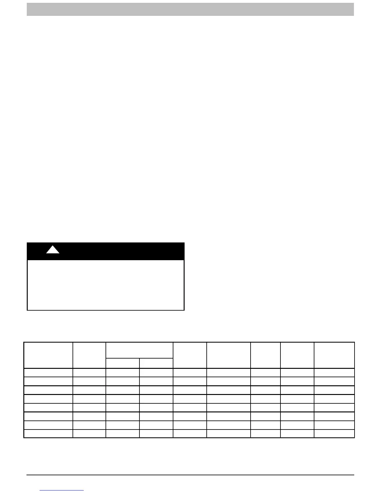
Table 10 – Electrical Data
UNIT SIZE
VOLTS--
HERTZ--
PHASE
OPERATING VOLTAGE
RANGE*
MAXIMUM
UNIT
AMPS
UNIT
AMPACITY#
MINIMUM
WIRE
SIZE
AWG
MAXIMUM
WIRE
LENGTH
FT (M)}
MAXIMUM
FUSE OR
CKT BKR
AMPS{
Maximum* Minimum*
040A030C 115--60--1 127 104 5.2 7.5 14 49 (14.9) 15
060B048C 115--60--1 127 104 8.6 11.7 14 31 (9.4) 15
080B048B 115--60--1 127 104 8.1 11.1 14 33 (10.1) 15
080B048C 115--60--1 127 104 8.1 11.1 14 33 (10.1) 15
080C060C 115--60--1 127 104 8.6 11.7 14 31 (9.4) 15
100C048C 115--60--1 127 104 7.3 10.1 14 36(11.0) 15
100C060C 115--60--1 127 104 11.9 15.8 12 36(11.0) 20
120D060C 115--60--1 127 104 11.9 15.8 12 36(11.0) 20
* Permissible limits of the voltage range at which the unit operates satisfactorily.
# Unit ampacity = 125 percent of largest operating component’s full load amps plus 100 percent of all other potential operating components’ (EAC, humidifier, etc.) full load
amps.
{Time--delay type is recommended.
}Length shown is as measured one way along wire path between furnace and service panel for maximum 2 percent voltage drop.