INSTALLATION INSTRUCTIONS Gas Furnace: WFAR
440 01 7104 02 39
Specifications subject to change without notice.
For vent termination clearance, references to National codes
are shown in Figure 51 for Direct Vent/2--Pipe system and
Figure 52 for Ventilated Combustion Air/Non--direct
Vent/1--Pipe system. For exterior termination arrangements,
refer to Figure 53 for Direct Vent/2--Pipe system and Figure 54
for Ventilated Combustion Air/Non-- Direct/1--Pipe system.
Contact Local code authorities for other requirements to and/or
exemptions from the National codes shown in the figures.
Roof termination is the recommended termination location.
Roof terminations provide better performance against
sustained prevailing winds. The roof location is preferred since
the vent and combustion air system is less susceptible to
damage or contamination. The termination is usually located
away from adjacent structures or other obstacles such as
inside corners, windows, doors or other appliances. It is less
prone to icing conditions, and it often has less visible vent
vapors.
Sidewall terminations may require sealing or shielding of
building surfaces with a corrosive resistance material due to the
corrosive properties of combustion products from the vent
system, as well as protection of adjacent structures.
NOTE: (Direct Vent/2--Pipe system ONLY) A factory accessory
termination kit MUST be used. See Table 11 for available
options.
NOTICE
RECOMMENDED SUPPORT FOR VENT
TERMINATIONS
It is recommended that sidewall vent terminations of over
24 inches (0.6 M) in length or rooftop vent terminations
of over 36 inches (1 M) in vertical length be supported by
EITHER the Direct Vent Termination Kit shown in Table
11 or by field-supplied brackets or supports fastened to
the structure.
When determining appropriate location for termination, consider
the following guidelines:
1. Comply with all clearance requirements stated in
Figure 51 or Figure 52 per application.
2. Termination or termination kit should be positioned where
vent vapors will not damage plants/shrubs, air
conditioning equipment or utility meters.
3. Do not locate termination directly into prevailing winds.
Termination should be positioned so that it will not be
affected by sustained prevailing winds over 30 mph,
wind eddy, such as inside building corners, or by
recirculation of flue gases, airborne leaves, or light snow.
4. Termination or termination kit should be positioned where
it will not be damaged by or subjected to foreign objects
such as stones, balls, etc.
5. Termination or termination kit should be positioned where
vent vapors are not objectionable.
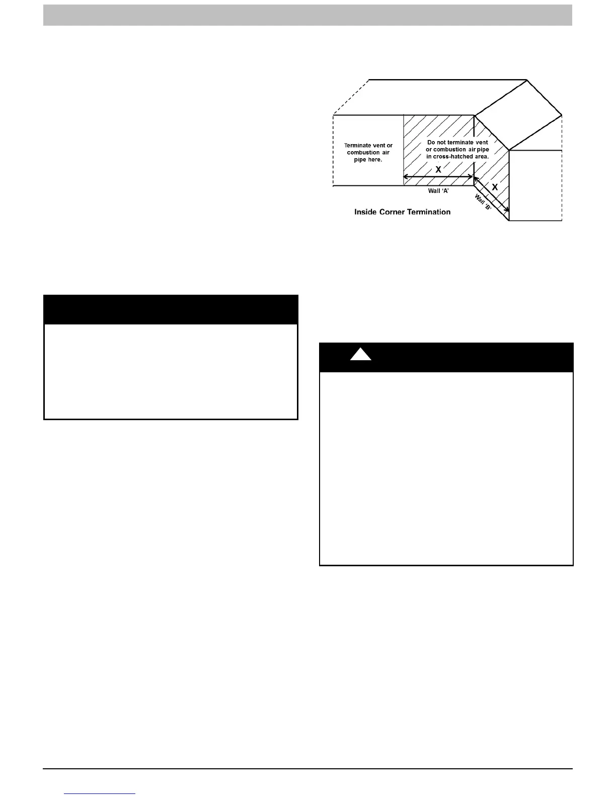
INSIDE CORNER TERMINATIONS
Corner terminations for Direct Vent (2--pipe) terminations are
permitted provided that:
1. The Direct Vent termination is located on the longer of
the two walls.
2. The Direct Vent termination is located at a distance
farther away from the inside corner than the length of the
adjacent wall
3. All other clearance requirements are met
Example:
1. The length of wall “A” is 15--ft and the length of wall “B” is
6--ft.
2. Therefore, the Direct Vent termination must be located
on wall “A”.
3. The Direct Vent termination must be located at least 6--ft.
away from the inside corner.
L14F028
Figure 39 -- Inside Corner Termination
Direct Vent / 2-Pipe System
Direct vent (2--pipe) vent and combustion air pipes must
terminate outside the structure. See Figure 51 for references to
vent clearances required by National code authorities.
Allowable vent and combustion air terminations are shown in
Figure 53.
!
WARNING
CARBON MONOXIDE POISONING HAZARD
Failure to follow the instructions outlined below for
each appliance being placed into operation could result
in carbon monoxide poisoning or death.
For all venting configurations for this appliance and
other gas appliances placed into operation for the
structure, provisions for adequate combustion,
ventilation, and dilution air must be provided in
accordance with:
U.S.A. Installations: Section 9.3 NFPA 54/ANSI
Z223.1 1--2012, Air for Combustion and Ventilation and
applicable provisions of the local building codes.
Canadian Installations: Part 8 of
CAN/CSA--B149.1--10. Venting Systems and Air
Supply for Appliances and all authorities having
jurisdiction.
Ventilated Combustion Air
The vent pipe for a Ventilated Combustion Air System must
terminate outdoors. See Figure 52 for references to vent
clearances required by National code authorities. Allowable
vent terminations are shown in Figure 54 The combustion air
pipe terminates in a well--ventilated attic or crawl space. Follow
the clearances as shown in Figure 56.
The combustion air pipe cannot terminate in attics or crawl
spaces that use ventilation fans designed to operate in the
heating season. If ventilation fans are present in these areas,
the combustion air pipe must terminate outdoors as a Direct
Vent System.
Non-Direct Vent / 1-Pipe System
The vent pipe for a Non Direct Vent (1--pipe) system must
terminate outdoors. See Figure 52 for references to vent