INSTALLATION INSTRUCTIONS Gas Furnace: WFAR
40 440 01 7104 02
Specifications subject to change without notice.
clearances required by National code authorities. Allowable
vent terminations are shown in Figure 54.
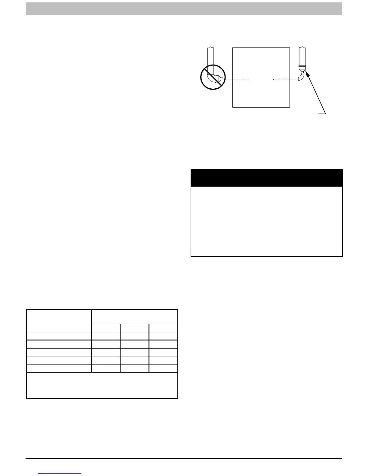
A combustion inlet air pipe to the outdoors is not required for a
Non--Direct Vent System. A 12--in. long section of pipe with a
tight radius 2--in. (51 mm) 90 degree elbow is required to be
attached to the furnace. See Figure 55. This short inlet air pipe
helps to ensure inlet air pipe away from occupants. An extra
elbow and/or five fee (1.5 M) of pipe may be used to
accomplish the sound attenuation function.
Termination Requirements for the
Provinces of Alberta and Saskatchewan
The Provinces of Alberta and Saskatchewan require a
minimum unobstructed distance of 4 ft. (1.2 M) from the
foundation to the property line of the adjacent lot for vent
termination of any appliance with an input over 35,000 btuh. If
there is less than 4 ft. (1.2 M) of unobstructed distance to the
property line of the adjacent lot, no type of vent termination is
permitted for appliances with inputs greater than 35,000 btuh.
There are no additional restrictions on unobstructed distances
greater than 8 ft. (2.4 M). All single, two-pipe and concentric
vents may be used, providing all other Code and
manufacturer’s requirements in these instructions are adhered
to. Refer to the appropriate Vent Termination section above for
locating the vent termination
If the unobstructed distance from the foundation to the property
line of the adjacent lot is no less than 4 ft. (1.2 M) and no
greater than 8 ft. (2.4 M), it will be necessary to re-direct the
flue gas plume. In this situation, a concentric vent kit cannot be
used. A 2-pipe termination (or single pipe termination when
permitted) that re-directs the flue gas away by use of an elbow
or tee, certified to ULC S636 from the adjacent property line
must be used. See Figure 55.
The concentric vent kit currently cannot be modified to attach
an elbow to the vent portion of the rain cap. A tee attached to
the rain cap could potentially direct the flue gas plume toward
the intake air stream and contaminate the incoming combustion
air for the furnace.
Refer to Figure 55 for terminations approved for use in Alberta
and Saskatchewan.
Size the Vent and Combustion Air
Pipes
General
Vent or Combustion Air
Pipe Diameters
Approved 2--pipe
termination fittings
2--in. 3--in. 4--in.
1 1/2--in. X N/A N/A
2--in. X N/A N/A
2 1/2--in. N/A X N/A
3--in. N/A X N/A
4--in. N/A X X
Note: Optional accessory 2--pipe termination brackets are
sized for 2--in. and 3--in. Pipe. If a termination bracket is re-
quired for a 4--in. termination, field fabricate the necessary
brackets and clamps.
Furnace combustion air and vent pipe connections are sized
for 2-in. (50 mm ND) PVC/ABS DWV pipe. The combustion air
and vent pipe connections also accommodate 60mm
polypropylene venting systems with outside diameters of
approximately 60 mm (2--3/8 inches). Any pipe diameter
change should be made outside furnace casing in vertical pipe.
Any change in diameter to the pipe must be made as close to
the furnace as reasonably possible. See Figure 40.
The Maximum Vent Length for the vent and combustion air pipe
(when used) is determined from the Maximum Equivalent Vent
Length in Table 14, minus the number of fittings multiplied by
the deduction for each type of fitting used from Table 15.
A93034
FURNACE
NOT IN
HORIZONTAL
SECTION
PIPE DIAMENTER
TRANSITION IN
SECTION
Figure 40 -- Combustion--Air and Vent Pipe
Diameter Transition Location and Elbow
Configuration
NOTICE
OPTIONAL CONFIGURATION FOR COMBUSTION
AIR INLET PIPE
In applications where there is a risk of excessive mois-
ture entering the combustion air inlet pipe, a moisture
trap may be added to the inlet pipe to help prevent
moisture from entering the furnace from the combus-
tion air inlet pipe. See Figure 57.
When sizing venting systems, the equivalent length of
the optional moisture trap (15 feet/5 M) must be taken
into account.
Combustion Air Inlet Moisture Trap
To prevent moisture from trickling into the furnace vestibule, a
trap can be installed in the intake air pipe near the furnace.
Connecting a drain line to the trap is recommended as trace
amounts of moisture will evaporate into the intake air stream. If
the combustion air inlet is located near a moisture exhaust
duct, or there are other concerns of excessive moisture being
drawn into the combustion air inlet, it is encouraged to connect
adrainlinetothetrap.
The trap can be constructed from a running tee of the same
diameter of the intake air pipe with EITHER a removable cap
attached to a 6-inch long pipe connected to the tee or the
External vent Trap Kit to help prevent contaminants from
entering the furnace. See
Figure 57.
The External Vent Trap Kit accessory may be used as a trap for
the combustion air inlet pipe if a large amount of moisture must
be removed. The drain line may be connected to the same
drain as the furnace condensate and the evaporator coil
condensate line ONLY if the inlet air trap drain and the
evaporator coil drain empty into an open segment of pipe
above the drain, See
Figure 13. When using the External Vent
Trap Kit, refer to those instructions for proper drain
connections.
The tee may also be connected to the intake air pipe on the
side of the casing. See
Figure 57.
In any configuration, it will be necessary to add the equivalent
length of the tee (15 feet/5 M) to the Total Equivalent Vent
Length of the venting system.