INSTALLATION INSTRUCTIONS Gas Furnace: WFAR
440 01 7104 02 43
Specifications subject to change without notice.
3. Pilot drill the screw holes for the adapter in the casing
and attach the vent pipe adapter to the furnace with
sheet metal screws
4. Slide the end of the rubber vent coupling with notches in
it over the standoffs on the vent pipe adapter.
5. Insert a length of vent pipe through the coupling into the
outlet of the vent elbow.
6. Tighten the clamp around the outlet of the vent elbow.
Torque the clamp to 15 lb--in.
NOTICE
The following instructions are for PVC/ABS DWV vent
piping, only. DO NOT USE THESE TECHNIQUES FOR
POLYPROPYLENE VENT PIPING SYSTEMS. See the
polypropylene vent system manufacturer’s instructions
for installing polypropylene venting systems.
Install the remaining vent and combustion air pipes as shown
below. It is recommended that all pipes be cut, prepared, and
preassembled before permanently cementing any joint.
1. Working from furnace to outside, cut pipe to required
length(s).
2. De--burr inside and outside of pipe.
3. Chamfer outside edge of pipe for better distribution of
primer and cement.
4. Clean and dry all surfaces to be joined.
5. Check dry fit of pipe and mark insertion depth on pipe.
6. Insert the vent pipe into the vent elbow.
7. Torque clamp on vent elbow 15 lb--in.
8. Torque clamp on vent coupling 15 lb--in.
9. Insert the combustion air pipe into the adapter.
10. Pilot drill a screw hole through the adapter into the
combustion air pipe and secure the pipe to the adapter
with sheet metal screws. DO NOT DRILL INTO
POLYPROPYLENE VENT PIPES. Use an optional
accessory vent coupling, if needed.
11. Seal around the combustion air pipe with silicone or foil
tape. SILICONE SEALERS MAY NOT BE
APPROPRIATE FOR POLYPROPYLENE VENT
SYSTEMS. SEE POLYPROPYLENE VENT SYSTEM
MANUFACTRUER’S INSTRUCTIONS.
12. After pipes have been cut and preassembled, apply
generous layer of cement primer to pipe fitting socket
and end of pipe to insertion mark. Quickly apply
approved cement to end of pipe and fitting socket (over
primer). Apply cement in a light, uniform coat on inside of
socket to prevent buildup of excess cement. Apply
second coat. DO NOT CEMENT POLYPROPYLENE
FITTINGS.
13. While cement is still wet, twist pipe into socket with
1/4--in. turn. Be sure pipe is fully inserted into fitting
socket.
14. Wipe excess cement from joint. A continuous bead of
cement will be visible around perimeter of a properly
made joint.
15. Handle pipe joints carefully until cement sets.
16. Horizontal portions of the venting system shall be
supported to prevent sagging. Space combustion air
piping and vent piping hangars as shown in the table
below. Support pipes using perforated metal hanging
strap or commercially available hangars or straps
designed to support plastic pipe.
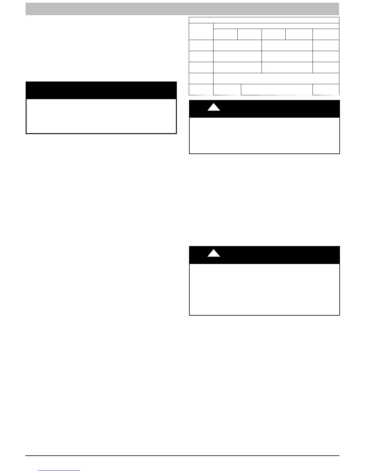
Hangar Spacing
Material
Pipe Diameter
1½-in.
(38-mm)
2-in.
(51-mm)
2½-in.
(64-mm)
3-in.
(76-mm)
4-in.
(102-mm)
PVC Sch
40
36-in.
(914-mm)
42-in.
(1067-mm)
48-in.
(1219-mm)
CPVC
36-in.
(914-mm)
42-in.
(1067-mm)
48-in.
(1219-mm)
ABS
36-in.
(914-mm)
42-in.
(1067-mm)
48-in.
(1219-mm)
Polyprop
ylene
40-in.
(1000-mm)
SDR 21
&26
30-in.
(762-mm)
36-in.
(914-mm)
42-in.
(1067-mm)
! CAUTION
FURNACE RELIABILITY HAZARD
Failure to follow this caution may result in nuisance short
cycling, frozen vent termination, and/or no heat.
Slope the vent and combustion air piping downward towards
furnace at a minimum of 1/4--in. per linear ft. of pipe.
17. Slope the vent and combustion air piping and downward
towards furnace. A minimum slope of at least 1/4 in. per
linear ft.(1 in. per 4 ft.) with no sags between hangers is
required. See Caution Box below
18. Complete the vent and combustion air pipe installation
by connecting the concentric vent or by installing the
required termination elbows as shown in Figs. Figure 53,
Figure 54 and Figure 55.
19. For Ventilated Combustion Air Termination, See
Figure 56.
20. Use appropriate methods to seal openings where
combustion air pipe and vent pipe pass through roof or
sidewall.
!
WARNING
CARBON MONOXIDE POISONING HAZARD
Failure to follow this warning could result in personal
injury or death.
DO NOT use cement to join polypropylene venting
systems. Follow the polypropylene venting system
manufacturer’s instructions for installing polypropylene
venting systems.
Optional Installation of the vent pipe
NOTE: DO NOT USE THIS TECHNIQUE FOR
POLYPROPYLENE VENTING SYSTEMS.
This option provides a disconnect point for the vent pipe. The
vent pipe must be cemented to the plastic vent pipe adapter to
maintain a sealed vestibule. See Figure 49.
1. Insert a length of vent pipe through the casing into the
outlet of the vent elbow.
2. Slide the plastic vent pipe adapter over the length of the
vent pipe down to the furnace casing. Mark the pipe
where it is flush with the outlet of the adapter.
3. Remove the pipe from the furnace and the adapter and
cut off any excess pipe.
4. Clean and prime the end of the pipe that is flush with the
vent adapter with a primer that is appropriate for the type
of pipe being used.
5. Re--insert the pipe through the casing into the vent
elbow.