20
6. From the front of boiler, remove the
straight connector end of the flexible
hose from the top of the condensate
trap.
7. Reverse the flexible hose and pass the
straight connector end through the new
hole in the left hand casing panel. Push
the straight connector firmly onto the
condensate outlet connection of the
condensing heat exchanger - push on
at least 20 mm.
8. Refit the left hand casing panel to
the rear panel using the reverse
procedure, ensuring all fixing screws
are used.
9. Remove the trap from the mounting
bracket.
10. Unscrew and remove the trap
mounting bracket from the left side
panel.
11. Fix the trap mounting bracket to
the wall adjacent to the boiler in the
required position.
The top of the trap must be below
the condensate connection on the
boiler.
6.9 Relocate the Trap
To re-locate the factory-fitted trap
outside the boiler casing, use the
following procedure:
This procedure must be carried out
before the boiler is installed.
1. Remove the top casing panel(s) from
the boiler.
2. Unscrew and remove the screws
fastening the left side panel to the
rear casing panel of the boiler.
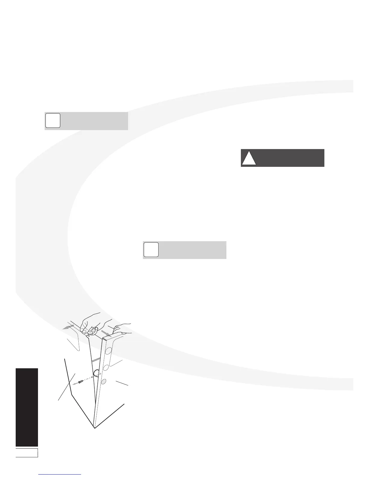
3. Carefully separate the left side and rear
panels just enough to gain access to
the condensate outlet on the left rear
of the condensing heat exchanger (see
Figure 6-4).
4. Push out pre-cut 'knock-out' from
the condensate outlet hole in the rear
of left side casing panel.
5. Remove the right angle end of the
flexible condensate discharge hose
from the outlet connection on the
condensing heat exchanger.
Condensate
Disposal
12. Re-fit the trap to the mounting
bracket.
The mounting bracket supplied with
the trap must be used - the trap
should not be supported by the
condensate pipework only.
13. Connect the flexible condensate
hose to the trap, pushing the right
angle hose connector onto the trap
inlet connection.
The flexible hose must fall
continuously from the outlet to the
top of the trap.
NOTE
!
Figure 6-4: Remove the condensate trap