28
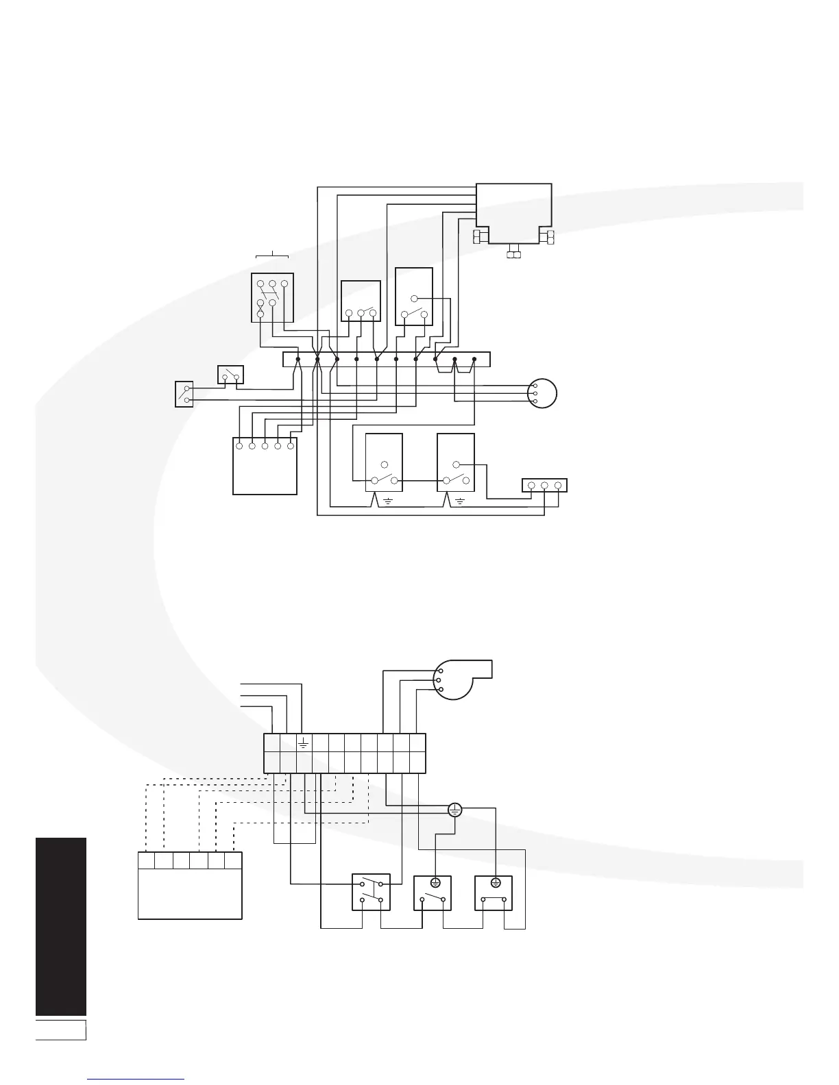
8.6 Boiler Control Panel Wiring Diagrams
Electrical
Figure 8-6: Wiring Diagram - Kitchen/Utility models
R
R
Y
G/Y
CH
OFF
N
L
HW
OFF
CH
ON
HW
ON
Br
Bl
2A
4B
1A
Br
Br
5B
1
Bl
G/Y
Br
C
C
2
G/Y
Bl
BOILER FEED
4321
DHW - ON
CENTRAL HEATING
65 97 8
N
L
E
G/Y
R
Br
10
DHW - OFF
N
L
E
Bl
Br
G/Y
NL
G/Y
Bl
Br
L
E
N
Br - Brown, Bl - Blue, R - Red, G/Y - Green/Yellow, Y - YellowColour code:
OPTIONAL:
Grant Electronic
7-day plug-in programmer
(Ref. EPKIT)
Boiler
On/Off Switch
Control
Thermostat
Limit
Thermostat
Mains Supply:
Use 2 pole isolator
with power ‘ON’ indicator
Note:
MUST
The factory fitted link between
terminals 1 & 4 be removed
when the plug-in programmer is
fitted to the control panel.
Burner
Boiler
Terminal Block
Figure 8-5: Boiler House models with 3-port valve control system
1
C 2
1
C 2
1
C 2
L N E
2 1
3
Pump
E
N
L
Blue
Green/Yellow
White
Orange
Grey
L N E
1 2 3 4 5 6 7 8 9 10
Frost
Thermostat
Pipe
Thermostat
(if fitted)
1 3 4 N L
Grant 2-Channel
Wall Mounted Programmer
(Ref. ESKIT)
Cylinder
Stat
Room
Stat
3-Port
Mid Position
Zone Valve
Burner
Wiring Centre
Overheat
stat
Control
stat
240 V
50 Hz