40
It is important that the following
commissioning procedure is carried out
to ensure safe and efficient operation of
the boiler.
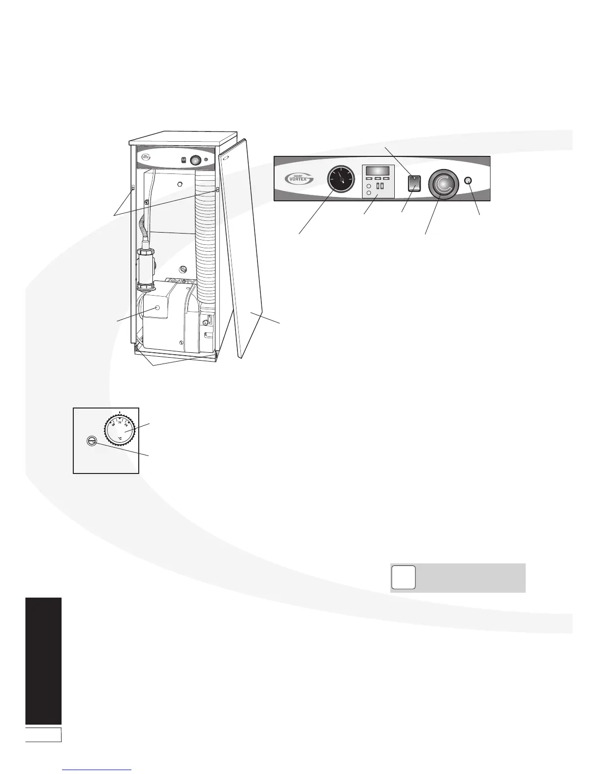
To access the controls, remove the front
panel (pull forward at the top then lift off).
The controls are shown in Figure 10-1.
10.1 Before Switching On
1. Ensure the boiler On/Off switch
(Kitchen/Utility models only) is set to
OFF. For Boiler House models, check
that all system controls are set to OFF.
2. Check that the high limit thermostat
bulb and both thermistor sensors are
correctly located in their respective
pockets. Refer to Figures 5-1 or 5-4
as required.
10 Commissioning
Programmer
(if fitted)
Pressure gauge
(System models only)
Boiler
thermostat
Overheat
thermostat
reset button
(under cover)
On/Off
switch
OVERHEA
T
RESET
Figure 10-1: Boiler controls (Kitchen/Utility model shown)
Commissioning
Check condition of both thermostat
capillaries, not damaged, broken,
kinked or crushed.
3. Remove the nuts and washers securing
the front cleaning door. Withdraw the
door - take care as it is HEAVY!
4. Check that the turbulators are in
position and that the ends are vertical.
5. Check that the baffles are in position.
Refer to Figures 11-1, 11-2, 11-3 or
11-4 as required.
6. Re-fit the cleaning door and check it
is fitted correctly and that a good seal
is made.
7. Remove and check the burner.
Check burner head is correct (and
set correctly on the 48/58 and 58/70
models). Refer to Section 2.3 and figure
11-8.
Check electrodes are set correctly.
Refer to Figure 11-5 or 11-7 as required.
Check the nozzle is correct for the
output rating required. Refer to Section
2.3
If the 15/21 model is down rated to 15
kW, the burner air adjuster disc must
be adjusted to setting B as described in
Section 10.6. Refer also to Section 2.3.
If a 15/26 model is down rated to 20
or 15 kW, the burner head must also
be changed to a T1 head. See Section
11.4. Refer also to Section 2.3.
8. Check that the water system has been
vented (and pressurised if sealed
system) and there are no leaks.
NOTE
!
Figure 10-2: Boiler House dual thermostat (on top of boiler)
Boiler thermostat
Overheat thermostat
reset button (under plastic cap)