30
9.1 Air Supply
A sufficient permanent air supply to
the boiler should be provided for the
following reasons:
• For proper combustion of fuel and
effective discharge of combustion
products to the open air.
• For the ventilation of any confined
space in which the boiler is installed to
prevent overheating of the boiler and
any equipment in and near the boiler.
It should be both the designer's and
installer's concern that the air required
for these functions be introduced so as
to cause as little discomfort as possible
to the building occupants and thus
to offer them the least temptation to
obstruct the ventilators.
Further details may be obtained from BS
5410:1:1997.
For a boiler fitted in a compartment,
which is ventilated as shown, no
additional allowance is necessary.
Open flue - Extract fans, where needed,
should be in accordance with Section
4.4 in BS 5410 Part 1 1997.
All ventilation areas given are for
domestic applications and relate to
the full output rating of the boiler.
For installations in older dwellings
(constructed prior to the introduction
of Approved Document L1A 2006) the
first 5 kW of output can be ignored. For
all other cases refer to BS 5410 Part 2
1978.
9 Flue System and Air Supply
Flue System and
Air Supply
NOTE
!
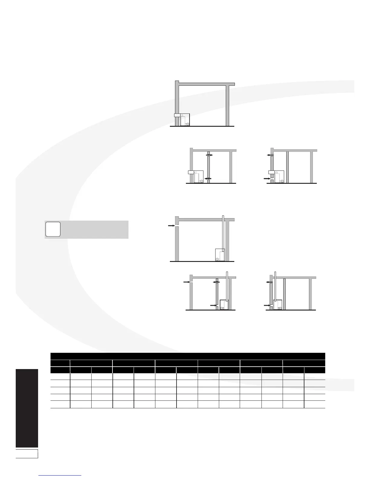
Figure 9-1: Air supply for room sealed balanced flue boilers
Figure 9-2: Air supply for conventional flue boilers
BOILER IN
ROOM
Room sealed balanced flue
no ventilation required to room
BOILER IN
COMPARTMENT
Room sealed balanced flue
compartment ventilated from room
Room sealed balanced flue
compartment ventilated from outside
B
B
A
A
Output
Area
Vent A
Vent B
Vent C
Vent D
Vent E
cm
2
116
232
116
232
348
in
2
18
36
18
36
54
cm
2
143
286
143
286
429
in
2
23
46
23
46
69
cm
2
198
396
198
396
594
in
2
31
62
31
62
93
cm
2
253
506
253
506
759
in
2
40
80
40
80
120
cm
2
319
638
319
638
957
in
2
50
100
50
100
150
cm
2
385
770
385
770
1155
in
2
60
120
60
120
180
VORTEX Pro boilers - Ventilation areas
58/70 kW46/58 kW36/46 kW26/36 kW15/26 kW15/21 kW