Distances measured to rim of terminal.
Clearances recommended by Grant UK
in accordance with British Standards
and Building Regulations.
1. An opening means an openable
element, such as an openable
window, or a permanent opening
such as a permanently open air
vent.
2. Notwithstanding the dimensions
given, a terminal should be at
least 300 mm from combustible
material, e.g. a window frame.
3. A way of providing protection of
combustible material would be to
fit a heat shield at least 750 mm
wide.
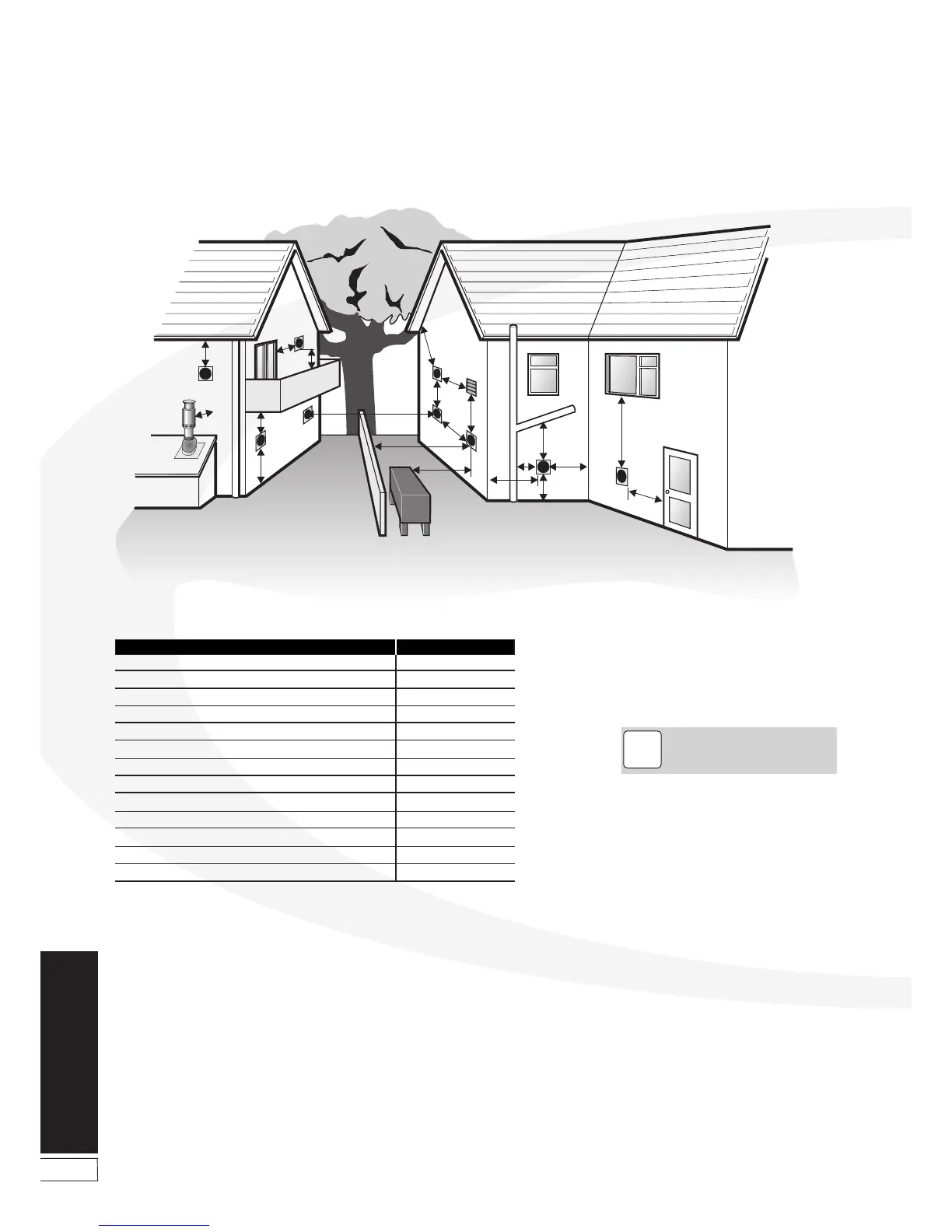
Figure 9-10: Clearances for Balanced flue terminals
A Below a gutter or sanitary pipework
B Horizontal from an opening, air brick or window
C Above ground or balcony level
D Below eaves or balcony
E From an internal or external corner
F From a terminal facing the terminal
G From a surface facing the terminal
H Vertical from terminals on the same wall
I Horizontal from terminals on the same wall
J Below an opening, air brick, window etc.
K From vertical sanitary pipework
L Vertical flue from a wall
M From an oil storage tank
Min. distance (mm)Terminal position
600 *
600
300
600 *
300
1200
600
1500
750 **
600
300
750
1800
NOTE
!