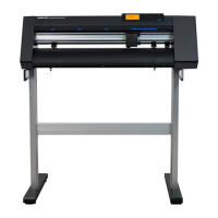
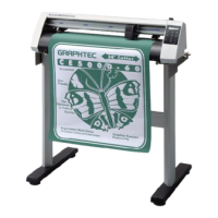
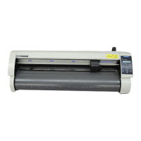
Do you have a question about the GRAPHTEC CE7000-40 and is the answer not in the manual?
Instructions for safely handling sharp cutter blades to prevent bodily injury.
Guidance on handling cutter plungers, ensuring blades are retracted when not in use.
Lists and describes the standard accessories included with the cutting plotter.
Guide on connecting the plotter to a computer via USB, LAN, or RS-232C interface.
Details on cutter plunger nomenclature, structure, and blade length adjustment.
Instructions for securely attaching and removing tools like cutter plungers and pens.
Procedures for loading roll and sheet media, including alignment and push roller settings.
Steps for safely connecting the plotter to a power source and turning it on.
Guide on setting tool conditions (force, speed, acceleration, offset) for optimal cutting.
Procedure for performing test cuts to ensure optimal settings for media and blades.
Procedure to set a new origin point for cutting at any desired location.
Instructions for pausing, resuming, or quitting a cutting operation via the control panel.
Function to cut specified numbers of data stored in the buffer memory.
Explanation of the ARMS system for scanning registration marks on media using sensors.
Procedures for setting and adjusting ARMS, including MARK SCAN Mode and sensor calibration.
Step-by-step guide for performing manual position adjustments using registration marks.
Guide to setting up the plotter's interface for USB, Network (LAN), and RS-232C connections.
Selecting the command type (GP-GL, HP-GL, AUTO) for plotter communication.
Choosing the output destination for data: USB Drive, Server (USB), or Server (LAN).
Performing data link by selecting files from USB memory for output to the plotter.
Step-by-step instructions for safely replacing the cutter blade in the plunger.
Solutions for common symptoms like no display, media wobbling, or position alarms.
Performing a self-diagnostic test to check plotter sensors and switches after power-on.
Detailed technical specifications for CE7000 models, including dimensions and performance.
| Model | CE7000-40 |
|---|---|
| Buffer Memory | 2 MB |
| Mechanical Resolution | 0.005 mm |
| Resolution | 0.005 mm |
| Media Type | film |
| Interface | USB |
| Command Sets | HP-GL, GP-GL |
| Rated Power Supply | 100 to 240 V AC, 50/60 Hz |
| Power Requirements | 100 to 240 V AC, 50/60 Hz |
| Compatible OS | Windows |
| Drive Method | Servo motor |
