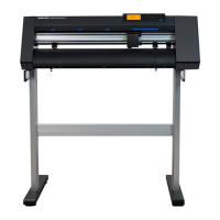
How do I fix E03005 error on GRAPHTEC Plotter?
- KKatelyn BriggsSep 15, 2025
To correct error E03005 on your GRAPHTEC Plotter, where an unsupported character set was specified, specify a character set that can be used by the device.
How do I fix E03005 error on GRAPHTEC Plotter?
To correct error E03005 on your GRAPHTEC Plotter, where an unsupported character set was specified, specify a character set that can be used by the device.
Why my GRAPHTEC CELITE-50 does not recognize the media?
If your GRAPHTEC Plotter isn't recognizing the media, several factors could be the cause. Here's what to check: * If the device is exposed to direct sunlight or intense light, block the light source or move the device. * If you're using transparent media, disable the Media width detection feature. * There may be a problem with the Width detection sensor, you can try to adjust it. If none of these steps work, there may be a problem with the device. Contact your sales representative or nearest Graphtec dealer.
What to do if GRAPHTEC CELITE-50 Plotter shows error E02006?
If your GRAPHTEC Plotter displays error E02006, it means data exceeding the cutting area has been received. To resolve this, check the data, the size and cutting area of the media, the scale settings, and the size of steps settings.
What to do if GRAPHTEC Plotter cannot scan registration marks?
If your GRAPHTEC Plotter fails to scan registration marks, verify the registration mark scanning positions.
What does E03006 error mean on GRAPHTEC CELITE-50?
To fix error E03006 on your GRAPHTEC Plotter, where the command coordinates are outside the cutting area, execute the command with coordinates within the cutting area.
What to do if GRAPHTEC Plotter shows error E05003?
If your GRAPHTEC Plotter displays error E05003, it means the available area on the media to copy is too small. You can either use a larger media or confirm the copy starting position.
What does E04022 error mean on GRAPHTEC CELITE-50?
If your GRAPHTEC Plotter displays error E04022, it means the cancel operation was performed by the user. Redo the process to continue.
What to do if GRAPHTEC CELITE-50 shows E04023 to E04025 error?
If your GRAPHTEC Plotter displays errors E04023 to E04025, and registration marks could not be scanned, try the following: * Readjust the sensor levels. * Change the color used to print the registration marks. * Confirm the media. * Review the positions where the registration marks are printed.
What to do for E04006 error on GRAPHTEC CELITE-50?
If your GRAPHTEC Plotter displays error E04006, it means the data volume exceeded the I/O buffer with segment area registration marks. To solve this, reduce the amount of data.
What causes E04002 error on GRAPHTEC CELITE-50?
If your GRAPHTEC Plotter shows error E04002, the configurable range for distance adjustment has been exceeded. Set a smaller distance adjustment value to resolve this.
Lists all included accessories with their model numbers and quantities for the cutting plotter.
Identifies and explains the function of each part of the cutting plotter, including the operation panel and carriage.
Explains the various screens, buttons, and operations available on the device's touch panel interface.
Details the HOME screen buttons, other buttons, and screen navigation for operating the device.
Describes input screens, drum selection, list selection, position keys, instruction screens, and sleep mode.
Provides guidance on securing adequate installation space and dimensions for the plotter.
Specifies the required clearance around the main unit for proper operation and media handling.
Details compatible media sizes and illustrates the cutting area specifications for sheet and roll media.
Lists supported media widths and sizes, referencing carrier sheet use for non-standard widths.
Shows diagrams illustrating the cutting area based on media type and margin settings.
Guides users on downloading and installing necessary device drivers and application software for computer connection.
Explains the procedure for connecting the AC adapter and turning on the cutting plotter.
Details how to connect the cutting plotter to a computer using a USB cable after driver installation.
Outlines the initial setup process, including language and unit selection upon first power-up.
Explains how to adjust the blade depth of the cutter pen for optimal cutting performance.
Provides instructions and cautions for adjusting the blade depth to prevent damage and ensure proper cuts.
Details how to set the media set levers to lock or release the media for stable feeding.
Guides users on adjusting push roller positions to suit media width for secure media transport.
Explains the steps for loading sheet media, including proper alignment with push rollers and front guide.
Step-by-step instructions for loading sheet media by aligning it against the push rollers.
Instructions for loading sheet media when the push rollers are released, focusing on alignment and scanning.
Describes the process of safely removing sheet media from the device after cutting.
Explains how to select and confirm registered cutting conditions (CONDITION NO.) for specific tools and media.
Provides important notes regarding the cutting origin position and its impact on data creation and cutting accuracy.
Details how the cutting origin position varies with settings like tilt correction and margin.
Explains how the cutting area is affected by media type and margin settings for data creation.
Lists the methods and software required for sending cutting data from a computer to the plotter.
Provides guidance on routine maintenance, cleaning the cutter pen, and proper storage of the device.
Instructions on how to clean the cutter pen to maintain cutting quality, including cautions.
Introduces the concept of Printing & Cutting and the two main functions available for this process.
Explains the simple method of scanning media edges to predict cutting positions without registration marks.
Details how to measure and input offset values to compensate for printing displacement in simple P&C.
Describes the high-precision method using registration marks scanned by the sensor for accurate cutting.
Explains the two types of registration marks and their recommended placement on the media.
Illustrates the two types of registration marks (Type 1 and Type 2) and their usage guidelines.
Shows diagrams and dimensions for arranging registration marks on the media edge with margins.
Explains how the device automatically searches for registration marks within defined areas.
Guides users through the process of creating registration marks and cutting data using Graphtec Pro Studio.
Step-by-step instructions for creating registration marks using the Graphtec Pro Studio software.
Instructions for creating registration marks using the Cutting Master 4 software.
Explains how to load and cut using roll media, including assembling the roll media stocker.
Provides instructions for assembling the roll media stocker components onto the main unit.
Details how to use a carrier sheet for cutting various types of media, including precautions.
Guides on attaching media to the carrier sheet, ensuring proper alignment and adhesion.
Explains the process of loading the carrier sheet itself onto the plotter's rollers.
Describes how to set up and use a drawing pen for plotting applications.
Instructions for inserting and securing a drawing pen into the pen adapter using different screws.
Details how to attach the pen adapter to the tool holder and select the correct cutting condition.
Explains how to save data on a USB memory and perform cutting operations offline.
Guides on creating and saving cutting data files (.xpf, .plt) onto a USB memory device.
Step-by-step process for selecting files from USB memory and initiating the cutting job.
Describes how to cut data linked to barcodes printed on the media for automatic file selection.
Explains how to repeat cuts multiple times on the same or different media using stored data.
Details how to perform multiple copies of a cut on the same piece of media.
Guides on how to repeat cuts on different pieces of media, including media change procedures.
Explains how to set a new cutting origin point for precise job placement.
Describes how to expand the cutting area by adjusting media margins for left and right sides.
Instructions on how to stop or pause an active cutting operation.
Explains how to move the tool carriage to the home position after a cut for easier inspection.
Guides on setting and registering up to eight different cutting conditions (TOOL, SPEED, FORCE, etc.).
Details how to adjust tool selection and offset values to optimize cutting quality and corner accuracy.
Explains how to select the appropriate tool and adjust the offset value for precise cutting.
Describes how to adjust cutting speed and acceleration to control cutting time and quality.
Explains how to set the cutting speed, noting its impact on finish quality and time.
Details how to set acceleration, which affects cutting time and finish quality.
Explains how to set the speed for the tool when it is raised during cutting.
Provides settings for cutting thick media, including the tangential mode function.
Explains the tangential mode, which helps cut corners cleanly on thick media by controlling blade orientation.
Details the two modes of tangential operation (Mode 1 and Mode 2) for cutting thick media.
Allows setting overcut lengths for the start and end of lines when using tangential mode.
Guides on performing cut tests to confirm settings and adjust for optimal cutting results.
Describes how to perform a single test cut using current settings to check quality.
Explains performing three test cuts with adjusted settings to fine-tune force or offset values.
Covers settings for optimizing the scan mode and adjustment values for registration mark detection.
Guides on selecting the appropriate scan mode (1, 2, or 3) based on media type for mark detection.
Details procedures for confirming media state and registration marks for accurate scanning.
Explains how to scan and input correction values to align the cutting position with scanned marks.
Describes enabling automatic search for registration mark positions when auto scanning is active.
Covers settings related to media feeding and handling for stable operation.
Explains setting pre-feed distance to prevent media displacement and ensure stable feeding.
Details setting auto pre-feed with a specified feed length to stabilize media handling.
Describes automatically feeding and returning media by page length upon loading.
Guides on enabling/disabling media width detection and selecting media size for accurate loading.
Explains how to set communication commands (GP-GL, HP-GL) and related options.
Guides on selecting the communication command (GP-GL or HP-GL) for device operation.
Allows setting the origin point for HP-GL commands, choosing between "LOWER LEFT" or "CENTER".
Lets users select the HP-GL model emulation type (e.g., "7550" or "7586").
Allows adjusting the step size for GP-GL commands to ensure cutting accuracy.
Covers advanced settings for the operation panel, including language and beep options.
Allows setting the display language for the operation panel.
Allows setting the unit of measurement for lengths (Metric or Inch) on the panel.
Enables or disables the beep sound for key presses on the operation panel.
Provides guidance on troubleshooting common issues like the device not operating or irregular media movement.
Lists various error codes and messages, explaining their causes and solutions for GP-GL, HP-GL, and ARMS errors.
Explains how to perform self-tests and plot test patterns to verify the main unit's operational status.
Guides on plotting a self-test pattern to check the device's basic operational functions.
Details how to plot the "CUTTING PRO" test pattern to verify device operation.
Explains how to adjust the width detection sensor if errors occur related to media edge detection.
Guides on running diagnostic tests for sensors and switches to check the main unit's operating status.
Explains how to check the firmware version of the device's system.
Provides detailed technical specifications for the cutting plotter, including dimensions, speed, and OS compatibility.
Lists the product names and model numbers of all included supply items.
Shows diagrams illustrating the external dimensions and appearance of the cutting plotter.
Illustrates the hierarchical structure of the device's menu system for navigation.
Lists the default or initial values for various settings within the device's menu.
| Resolution | GP-GL: 0.005 mm, HP-GL: 0.025 mm |
|---|---|
| Media width | 50 mm |
| Type | Desktop |
| Cutting Speed | 500 mm/s |
| Interface | USB 2.0 |
| Blade Type | Supersteel Blade |
| Operating System Compatibility | Windows, macOS |
