Do you have a question about the GRAPHTEC CE7000-60 and is the answer not in the manual?
Lists all standard accessories included with the plotter, such as power cable, DVD, cutter plunger, and software activation code.
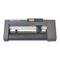
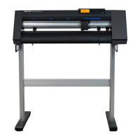
Identifies and describes the main parts of the plotter from front and rear views, including control panel, tool carriage, and rollers.
Provides instructions for assembling components like the roll-medium tray and stock shafts for proper plotter setup.
Guides on how to connect the plotter to a computer via USB, network (LAN), or RS-232C interfaces.
Details the structure, types, and nomenclature of cutter plungers (pens), including blade-length adjustment.
Instructions on how to securely attach and detach tools like cutter plungers or pens into the tool holder.
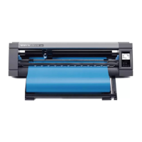
Step-by-step guide on loading roll and sheet media for different plotter models, ensuring correct alignment.
Explains how to correctly align push rollers for various media widths and lengths to ensure proper media feeding.
Describes the initial setup screen for display language and length unit settings upon first power-up.
Instructions on how to correctly connect the plotter to a power source and turn it on.
Explains the functions of the control panel's lamps and keys for operating the plotter.
Guides on setting the media feeding method (roll, sheet) after loading to ensure correct media handling.
Explains the PRE FEED function to prevent media slipping and ensure stable feed operations.
Details on setting tool conditions (force, speed, acceleration) for optimal cutting results.
Procedures for performing test cuts to optimize settings for media and blades, ensuring desired results.
Overview of Simple mode settings, their limitations, and how to switch between modes.
Instructions on how to check the plotter's available cutting area width.
How to raise or lower the tool (pen) using the control panel's 'TOOL' setting.
Manual movement of the tool carriage and media in steps or continuously using the POSITION key.
Procedure for setting a new origin point for cutting operations by moving the tool to the desired location.
How to rotate coordinate axes to change the cutting direction of the plotter.
Instructions on how to pause, resume, or quit a cutting operation via the control panel.
Introduction to the ARMS function, explaining its purpose for scanning registration marks on media.
Detailed steps for setting and adjusting the ARMS system, including SCAN MODE and ADJUST LEVEL.
Explains manual position adjustment using 2, 3, or 4 points, referencing registration marks or grits.
Step-by-step guide for performing manual position adjustments, including axis alignment and point selection.
Explains tangential mode for precise corner cutting, especially on thick media, including overcut settings.
How to set STEP PASS to control short lines for stable blade rotation and improved cut quality.
Adjusting the cutter blade tip angle for corners based on a reference angle to optimize cutting time.
Correcting deviations in cut or plotted line length by specifying a percentage of the total distance.
Setting perforated line patterns (0-7, OFF, USER) for easier separation of cut parts.
Setting initial blade control position to prevent media damage and ensure proper blade contact.
Adjusting offset force for blade alignment and direction control, especially in tangential mode.
Correcting misalignment between different tools, like pen and cutter, by entering adjustment values.
Optimizes cutting operation efficiency by minimizing media movement and tool replacement time.
Automatically feeds media when cut data is received to prevent shifting and ensure stable operation.
Automatically feeds media upon loading to prevent shifting and ensure stable media feed.
Adjusts media transfer speed during pre feed for heavy or slippery media to ensure stability.
Sets the speed of the tool carriage when raised, affecting overall cutting time and efficiency.
Configures how the tool moves to coordinates when raised (sequentially or to the last).
Adjusts the height of the tool when raised, especially for thick media, to ensure proper contact.
Guides on setting up USB, LAN, and RS-232C interfaces, including driver installation.
How to clear all output data from the plotter's buffer memory to reset operations.
Configuration steps for connecting via a network (LAN) interface, including DHCP and IP settings.
Settings and procedures for connecting the plotter via an RS-232C interface, including baud rate and parity.
Settings related to the menu display, including language selection and LCD contrast.
Settings for enabling or disabling media and push roller sensors for optimal media detection.
Settings related to the plotter's environment, such as fan suction and beep settings.
Settings for command processing, including selecting GP-GL, HP-GL, or AUTO commands.
Settings related to GP-GL commands, specifically the step size for travel distance.
How to enable or disable specific GP-GL commands that might affect data integrity.
Settings for the 'W' command affecting pen movement during arc cutting (TOOL UP/DOWN).
Settings related to HP-GL commands, specifically model ID response.
Setting resolution for circle commands in HP-GL, selecting between AUTO or DEFAULT.
How to select the output destination for data (USB memory, server) for data transfer.
Performing data link operations using USB memory to transfer data to the plotter.
Procedures for printing and cutting using barcodes for data linking, including standard and roll media barcodes.
Enabling automatic scanning of start marks for continuous operations to detect media skew.
Setting the time limit for communication connections before cancellation to prevent data loss.
Setting tolerance for media skew during continuous operation to prevent misalignment.
Explains creating registration marks and design data for printing and cutting using Graphtec software.
Describes adding and using barcode data for linking print and cut data, for standard and roll media.
Procedures for continuous cutting of multiple designs using roll media barcodes with Graphtec software.
Routine cleaning and storage procedures for the plotter to maintain its condition and lifespan.
Step-by-step instructions for safely removing and replacing the cutter blade in the pen.
How to clean the cutter pen to maintain performance and prevent build-up on blades.
Guidance on when and how to exchange the cutter plunger if the tip is worn down from friction.
Setting up an alarm to indicate when the cutter blade needs replacement based on cut distance.
Common symptoms, possible causes, and solutions for plotter operational issues.
How to print the current plotter settings list for reference and troubleshooting.
Procedure for creating a self-test pattern to check the plotter's operation and tool movement.
Creating a specific test pattern for checking cutting performance and blade condition.
How to output and check the plotter's received cutting data (dump list) for transmission accuracy.
Performing a self-diagnostic test to check plotter sensors, switches, and internal components.
Technical specifications for different CE7000 models, including CPU, cutting area, speeds, and interfaces.
Lists available optional accessories like stands and baskets, and consumable supplies for the plotter.
Provides external dimensions (W x D x H) for CE7000-40, CE7000-60, CE7000-130/160 models.
Visual representation of the plotter's menu structure for Simple and Normal modes.
Default settings for menu items like page length, interface, tool conditions, and initial feed.
| Mechanical Resolution | 0.005 mm |
|---|---|
| Buffer | 2 MB |
| Repeatability | ±0.1 mm |
| Cutting Force | 0.02 - 4.9 N (2 - 500 gf) |
| Interface | USB 2.0, Ethernet |
| Media Width | 700 mm |
| Display | 3.7-inch LCD |
| Connectivity | USB, Ethernet |
| Power Supply | AC 100-240V |
| Max. Media Width | 712 mm |
| Programmable Resolution | 0.025 mm |
| Commands | GP-GL / HP-GL™ (automatic detection) |
| Operating Environment | 10 to 35°C, 35 to 75% RH (non-condensing) |
| Resolution | GP-GL: 0.005mm, HP-GL™: 0.025mm |
| Cutting Width | 700 mm |
