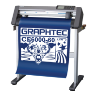
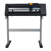
Do you have a question about the GRAPHTEC Cutting PRO FC2230 Series and is the answer not in the manual?
Precautions for safe handling and replacement of sharp cutter blades.
Guidelines for using and protecting the cutter pen tip during operation.
Safety measures to prevent injury from moving parts during operation.
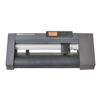
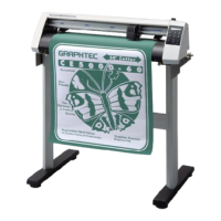
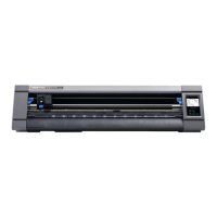
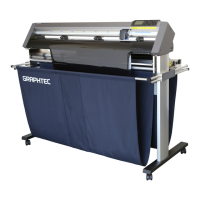
Details on different models and their fundamental specifications.
List and description of standard accessories provided with the plotter.
Overview of the plotter's main features and advanced functionalities.
Recommendations for installation environment and safe usage practices.
Instructions for routine cleaning, maintenance, and proper storage.
Comprehensive technical data including cutting area, speed, and power.
Diagrams showing the physical size and layout of the plotter models.
Identification of plotter parts and explanation of the control panel.
Procedures for installing the cutter pen and adjusting carriage height.
Steps for tilting the writing panel and loading cutting media.
Guide to turning on the plotter and its initialization sequence.
How to navigate menus and select plotter functions.
Explanation of special functions like command modes and pen control.
Diagnosing issues when the plotter doesn't operate and understanding error messages.
Solutions for common problems affecting cutting result quality.
Specifications and pin assignments for the RS232C serial interface.
Information on the Centronics parallel interface and its timing.
Steps for adjusting X/Y axis drivers, sliders, and belt tensions.
Procedures for adjusting roller pressure and sensor dog Y position.
Instructions for adjusting and replacing pen block assemblies.
Steps for Y bar replacement and adjusting perpendicularity precision.
Procedure for replacing the electrostatic adhesion plate.
Flowchart to identify and resolve issues with blade rotation.
Troubleshooting guide for when cutting media is not cut properly.
Diagnosing initialization errors and pen UP/DOWN operation issues.
Steps to diagnose and fix excessive backlash in X and Y axes.
Sequence flowchart for adjustments and location of electronic boards.
Checks on power unit, voltage switching, and protective circuits.
Guide to configuring DIP switches and clearing non-volatile RAM.
Procedures for default trimmer settings and motor/pen offset adjustments.
Steps for calibrating pen servo, force, and adjusting servo axes gain.
Calibrating pen interval for 2-pen models and using diagnostic test modes.
Restoring factory preset settings and configuring DIP switches.
Diagram showing the main units and their constituent parts.
Categorized lists of mechanical and board-related maintenance parts.
List of essential tools needed for plotter maintenance and repair.
Detailed parts list and diagrams for the 1-pen mainframe.
Parts list and diagrams for the 2-pen mainframe.
List of parts and diagrams for the plotter stand assembly.
Parts lists and diagrams for the control panel and unit.
Detailed parts lists and diagrams for X and Y drive units.
Parts list for optional roll stocker and pen block conversion details.
Diagrams illustrating the internal wiring connections of the plotter.
Circuit diagram and parts list for the Key Joint Board.
Circuit diagram and parts list for the Main Joint Board.
Circuit diagrams and parts lists for X, X-Y, and Pen Flex boards.
Circuit diagrams and parts lists for 1-Pen and Pen boards.
Circuit diagram and parts list for the High Voltage Board.
Detailed component lists for the Main Board.
List of various cables and AC power cords used with the plotter.
Guidelines for choosing a vacuum pump based on ratings and specifications.
Diagrams showing recommended installation positions for vacuum pumps.
Instructions for wiring the vacuum pump and associated safety precautions.
| Number of Tool Mounts | 1 |
|---|---|
| Model | FC2230 Series |
| Type | Cutting Plotter |
| Resolution | 0.025 mm |
| Repeatability Precision | ±0.1 mm |
| Interface | USB |
| Command Sets | GP-GL, HP-GL |
| Media Types | Vinyl, paper, film, etc. |
| Power Supply | AC 100 - 240 V, 50/60 Hz |

