26
nn
nn
n Connect the fuel shut-off solenoid.
nn
nn
n
If engine will not start after bleeding air from
the line, review trouble shooting section of
Engine Manual.
Engine dies when steering levers are engaged:
nn
nn
n If engine starts and runs but dies when either
steering lever is engaged, check the follow-
ing. Make sure the parking brake is released.
The steering levers cannot be engaged with
the parking brake on. With the key switch
“ON” and the seat switch engaged, check for
ground at the two yellow wires on the seat
switch. If there is ground at one wire but not
the other, either the seat switch is defective or
it is not being activated properly.
nn
nn
n If there is ground at both yellow wires on the
seat switch, check for ground at the yellow
wire on the parking brake switch. If there is
no ground, the wire between the seat switch
and the parking brake switch is broken. If
there is ground at the yellow wire, check for
ground at the white wire. If there is no ground
at the white wire, the parking brake switch is
defective and must be replaced.
NOTE: These tests must be performed with an
accurate voltmeter. Do not use a test light; the
amperage in this circuit is too low to properly
light a test light. This circuit is the ground side
of relay A.
ENGINE REMOVAL
To remove engine, disconnect: battery, fuel line,
electrical wires from engine, throttle and flex cou-
pling connected to coupling hub. Remove the four
engine mount bolts to the frame and drive belts from
clutch sheave. The engine can now be lifted out.
Consult your local authorized engine dealer for re-
pairs or repair parts.
WIRING CIRCUIT BOARD REMOVAL
Remove the circuit board from the console by
compressing the keeper in each of the three cir-
cuit board support spacers with needle nose
pliers (refer to Fig. 7). Slide the board past each
keeper when it is compressed.
Keeper
Spacer - Circuit Board Support
Part no. 423690
Needle Nose
Pliers
Console Side
95040
Circuit Board
Fig. 7
PARKING BRAKE ADJUSTMENT
(Refer to Fig. 8 and illustration page 37)
Adjust the right and left brake individually. Discon-
nect the right brake linkage rod (item 37). Adjust
the linkage pin attached to the left brake until it takes
14 lbs (62N) of pull at the top of the hand lever to
apply the parking brake. Adjustment of brake link-
age arm (item 43) may also be required. Connect
the right brake linkage.
97069A
0
10
20
30
40 50
Fig. 8
Disconnect the left brake linkage rod and adjust
the linkage pin attached to the right brake until it
takes 14 lbs (62N) of pull at the top of the hand le-
ver to apply the parking brake. Connect the left
brake linkage.
With both brakes connected it should take 28 lbs
(124N) of pull at the top of the hand lever to apply
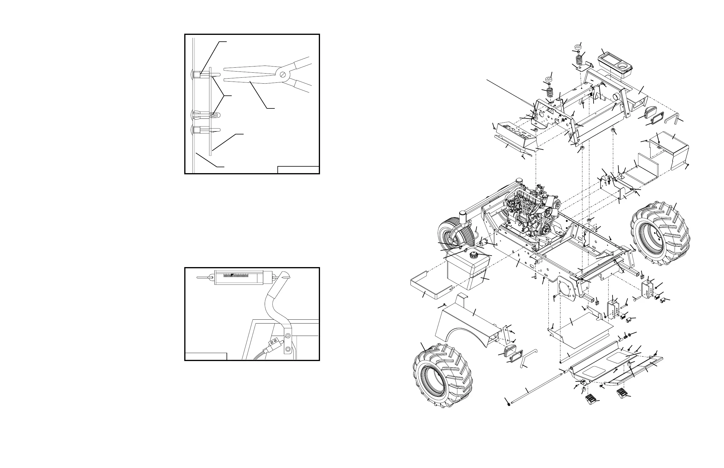
31
TRACTOR ASSEMBLY
1
3
4
4
4
4
8
8
15
17
18
19
20
21
22
23
23
24
24
28
29
30
31
32
33
34
35
36
37
38
38
39
40
41
42
42
43
43
44
44
45
46
47
47
48
49
49
50
51
52
53
54
55
55
56
56
57
58
58
59
59
60
61
66
66
67
68
68
69
69
70
71
71
70
62
69
68
68
63
63
59
05088
70
64
69
50
9
8
7
72
13
16
17
12
9
8
7
11
10
68
14
25
25
66
73
68
3
65
3
5
6
68
27
68
26
65
2
3
3
60
61