19
weights when not required.
nn
nn
n
Use extra care with grass catchers or other
attachments. These can change the stabil-
ity of the machine. Do not use grass
catcher on steep slopes.
nn
nn
n Do not operate without ROPS deployed.
nn
nn
n If machine is equipped with a fixed ROPS, al-
ways wear seatbelt.
nn
nn
n If machine is equipped with a foldable ROPS,
always wear seatbelt when ROPS is de-
ployed.
nn
nn
n Be certain that the seatbelt can be released
quickly if the machine is driven or rolls into
ponds or water.
nn
nn
n Check carefully for overhead clearances
such as, branches, doorways, or electrical
wires, before driving under any objects
and do not contact them.
STOPPING THE ENGINE
nn
nn
n Set the throttle at
1
/3 open. Allow engine to
idle at this setting for several minutes, then
move the throttle to slow idle.
nn
nn
n Move ignition switch to “OFF” position (up-
right) and remove key.
Always remove key from ignition
switch when leaving unit unattended or
when not in use.
Emergency shutdown of engine:
If the engine does not stop running with the
throttle at slow idle and the starter switch in the
“OFF” position, the following procedure will stop
the engine.
nn
nn
n Unplug the wires from the fuel shut-off sole-
noid (item 30, page 33).
nn
nn
n Push the engine stop lever forward toward
the radiator (refer to the Engine Manual’s il-
lustration showing the location of the engine
stop lever).
nn
nn
n It is important that the operator be familiar with
where the parts are located on the engine.
MOVING UNIT WITHOUT POWER
The hydro pumps are equipped with a dump valve
(Refer to Fig. 3) that allows the unit to be moved
without power by deactivating the pump. With the
dump valve lever in normal operating position
the fluid in the pump will make it difficult to
move the unit (even with the steering levers in
neutral position). The dump valve is located on
the bottom toward the right front of each hydro
pump. Activate the dump valve by rotating
counter-clockwise with a .625 inch wrench. Ro-
tate one revolution. When BOTH hydro pumps
are deactivated the unit becomes “freewheeling”
allowing it to be moved. Before the hydro pumps
become operational the dump valves must be
returned to their normal operating position.
Do not tighten above 120 in lbs (10 ft lbs)
(14Nm) maximum.
STEERING LEVER OPERATION
(refer to Fig. 4, page 21)
Do not move steering levers from
forward to reverse or reverse to
forward position rapidly. The sudden
change could cause loss of control or
damage to equipment.
The Grasshopper tractor is very
unstable without an attachment.
Move very slowly when attachment is
removed. Never carry passengers.
Fig. 3
Dump Valve
01096
38
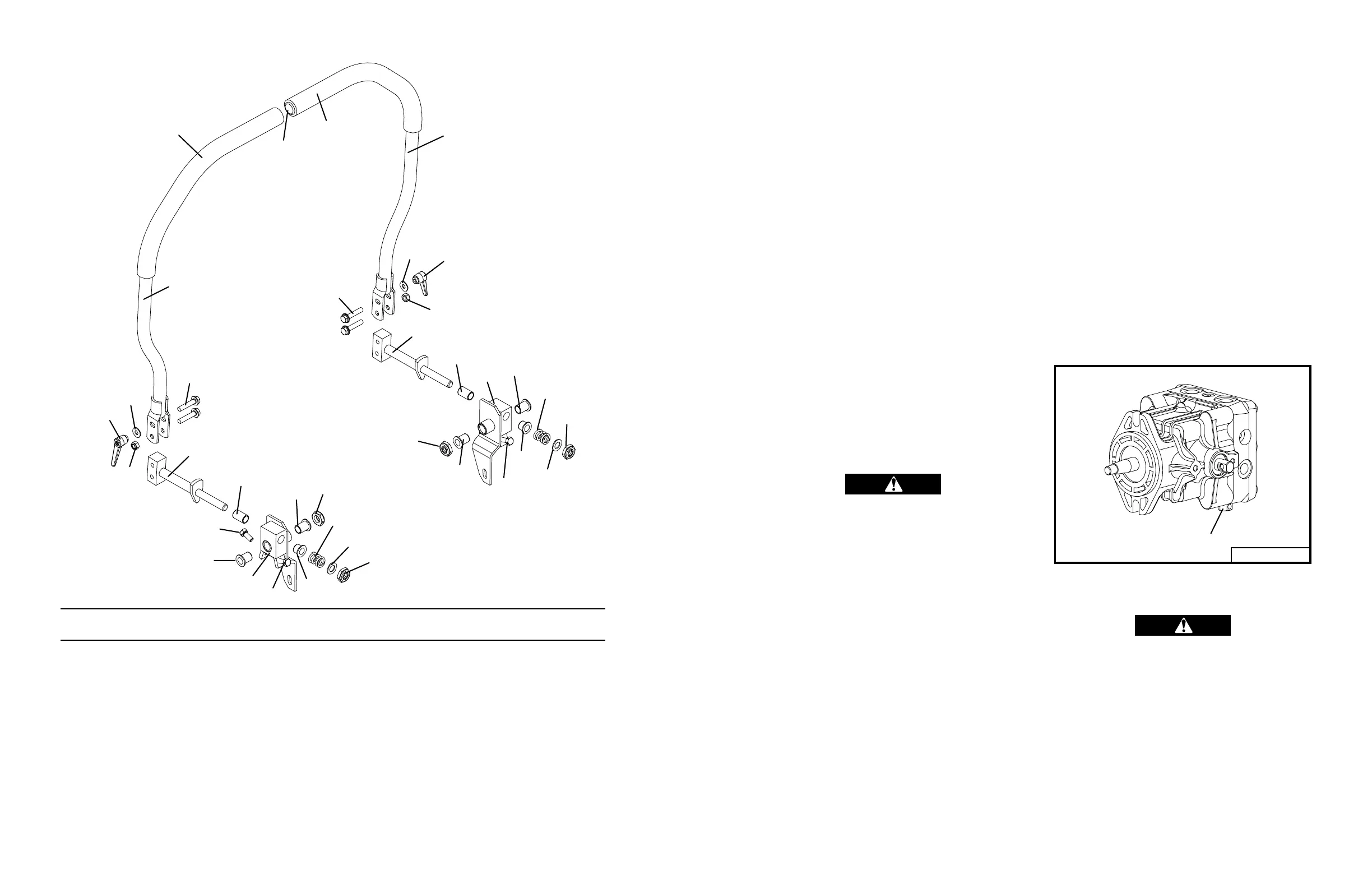
STEERING ASSEMBLY
1 604778 Steering Lever Assembly
(includes item 5 and 6)
2 643926 Steering Lever Mount
3 253195 Hex Whiz Bolt
4 253450 Nut -Nylon Insert
5 422179 Handle Grip - Foam
6 422095 Vinyl Cap
7 604771 Steering Pivot Rt. w/Stop & Bearings
8 604772 Steering Pivot Lt. w/Stop & Bearings
9 422559 Bearing w/Flange
10 422557 Bearing
11 257019 Washer
12 257063 Nylon Washer
13 422556 Bearing w/Flange
14 283324 Compression Spring
15 253470 Nut- Nylon Insert
16 243197 Stop Bolt
17 254438 Nut Adj. Lever
ItemItem
ItemItem
Item
OrderOrder
OrderOrder
Order
DescriptionDescription
DescriptionDescription
Description
No.No.
No.No.
No.
No.No.
No.No.
No.
ItemItem
ItemItem
Item
OrderOrder
OrderOrder
Order
DescriptionDescription
DescriptionDescription
Description
No.No.
No.No.
No.
No.No.
No.No.
No.
97023D
1
1
2
2
3
3
4
4
5
5
6
7
8
9
9
9
10
10
9
16
12
12
13
13
14
14
15
15
15
15
16
16
97023D
17
17
11
11