11
MOWER SETUP INSTRUCTIONS
Refer to corresponding parts illustrations for
your mower in the parts section.
Install gauge wheels as shown, making sure
spacers are in correct location and tighten
axle bolt locknut.
Check the bearings by spinning each wheel
to make sure it turns freely. Loosen axle bolt
nut slightly if they do not.
If mower is equipped with heavy duty fork
housings the forks have two sets of wheel
mounting holes. To obtain the lower cutting
range, position the axle bolt in the upper
holes. Use lower holes for the higher cutting
range.
Install mount arm assemblies to lift arm.
Remove one retainer from .75" pin and re-
move pin from mount arm assembly while
keeping torsion spring in position. Place in
brackets on lift arm and reinstall pin and re-
tainer (refer to fig. 3).
OPERATION
WARNING
Fig. 4
Fig. 3
Install the discharge opening restriction plate
or the discharge shield to deck and secure.
Model SL9861 requires a 50 pound weight on
the rear of the tractor unless the tractor has an
optional grasscatcher or dual tail wheels. For
700 series tractors a weight mount kit (part num-
ber 503220) and weight (part number 503218)
may be purchased.
A rear weight must be installed on
tractor without grasscatcher or dual
tail wheel option when operated with a
Model SL9861 mower deck.
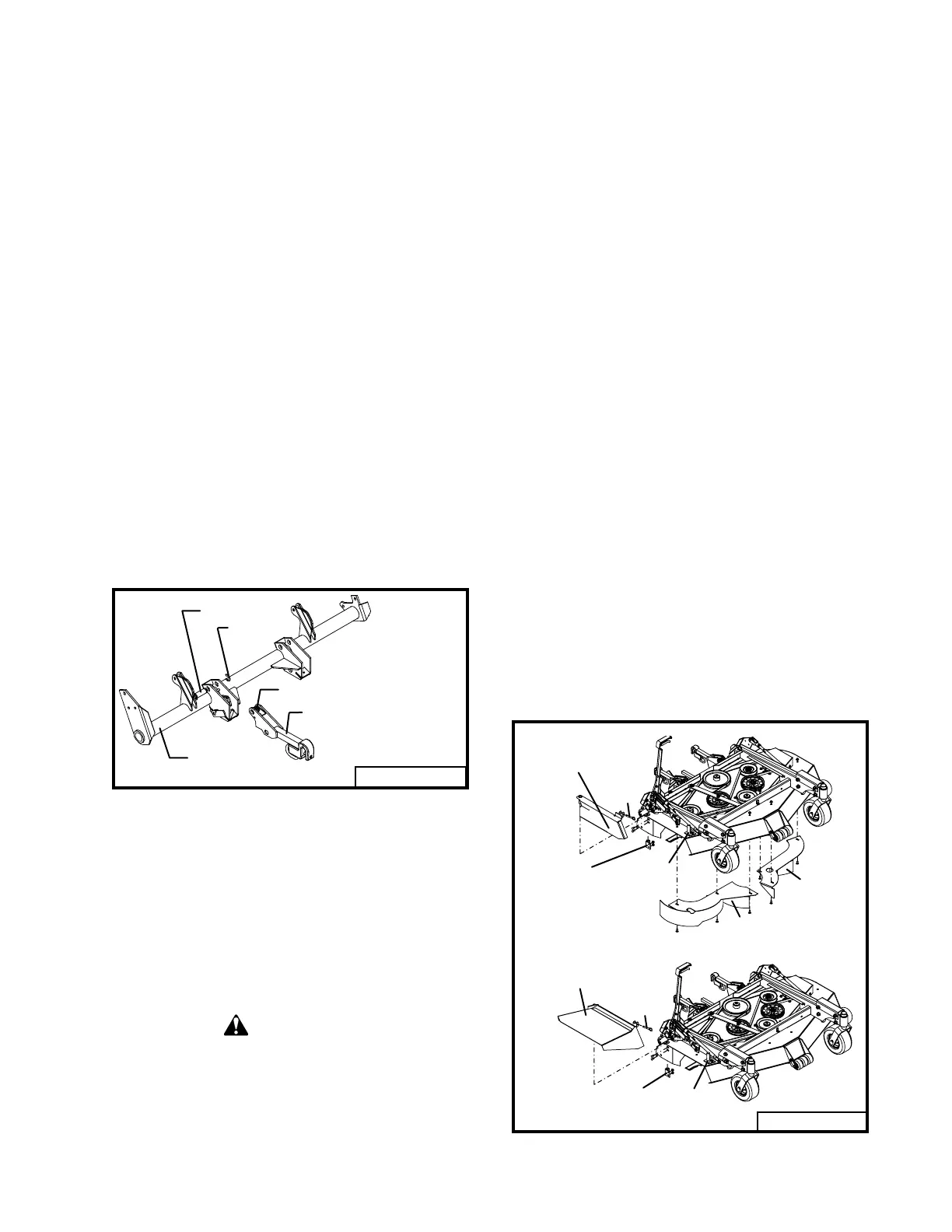
CONVERTING DECK FROM DOWN
DISCHARGE MULCHING TO SIDE
DISCHARGE
(refer to Fig. 4)
Remove the two belt shields from the top of
the mower deck.
Remove the discharge restriction plate from
the right side of the deck. Remove the hitch
pin from the clevis shaft, rotate the discharge
restriction plate away from the deck, and lift
it out of the pivot mount.
Remove the left and right front shrouds by
removing the two carriage bolts on each
shroud from underneath the deck.
There is only one part, the discharge shield,
that attaches to the mower deck converting it to
a side discharge mower.
Attach the discharge shield by sliding its
pivot shaft into the pivot mount.
Rotate the discharge shield to bring the clev-
is on the shield into contact with the clevis
shaft on the mower deck.
Secure shield in place with the .375 inch
hitch pin.
Install the two belt shields on top of the deck.
L i f t
A s s e m b l
0 0 0 3 7
M o u n t A r m A s s e m b l y
T o r s i o n S p r i n g
R e t a i n e r
. 7 5 P i n
R i g h t F r o n t
S h r o u d
L e f t F r o n t
S h r o u d
0 0 0 3 9
D i s c h a r g e
P i v o t
M o u n t
C l e v i s
S h a f t
H i t c h
P i n
R e s t r i c t i o n P l a t e
H i t c h
P i n
D i s c h a r g e
S h i e l d
P i v o t
M o u n t
C l e v i s
S h a f t
0 0 0 4 0
Rev. 09-00
 Loading...