13
Fig. 6
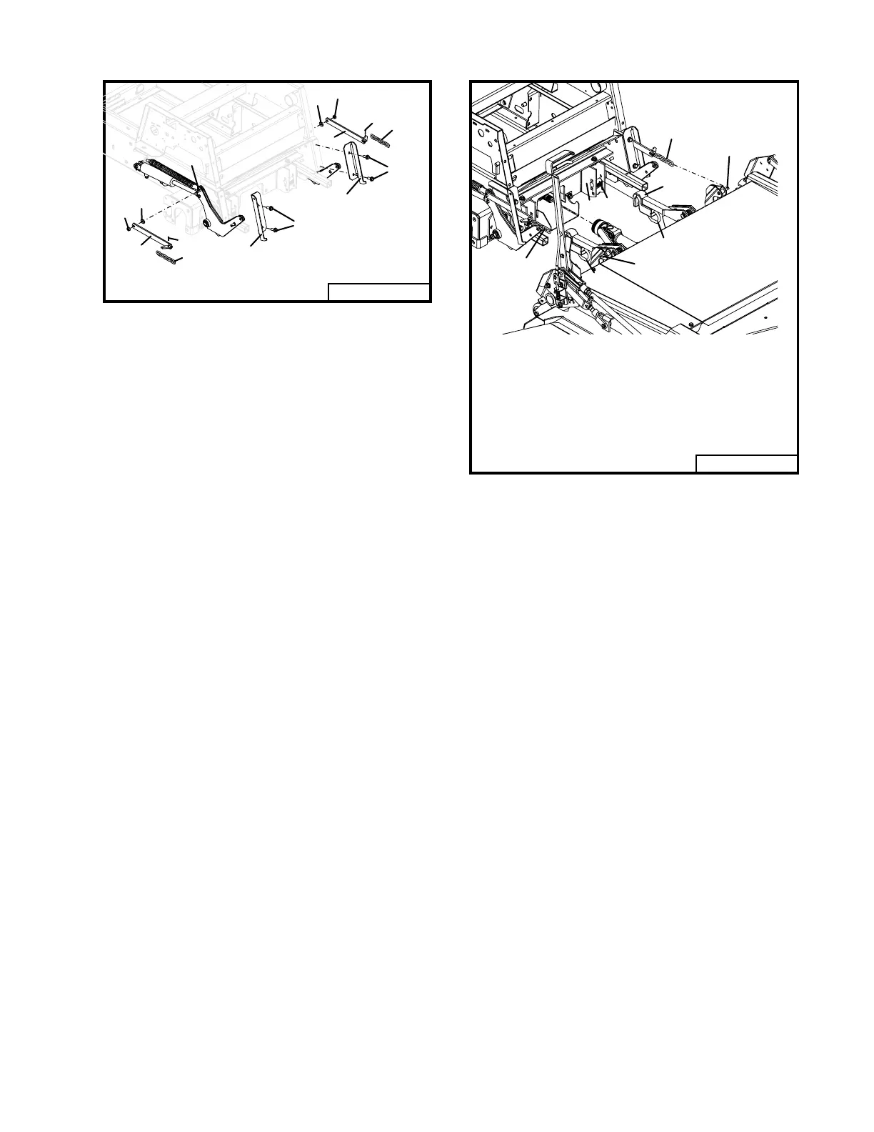
Fig. 7
Rev. 11-00
1
1
2
2
3
3
5
5
7
6
8
9
9
8
0 0 0 9 3
4
ATTACHING MOWER TO TRACTOR
(refer to Fig. 7)
Place the tractor and the mower on a level
surface with the deck stand (see illustration
page 28) in the down position.
Raise the deck arm mount clevises (item 3)
to their highest position using the deck lift
lever.
Pull out on the spring loaded deck mount
latch pins (item 1) and rotate 90° so that they
are in an open position.
Attach mower to tractor by placing the deck
arm mount clevises (item 3) over the attach-
ment mount bushings (item 2) bolted in the
attachment brackets. Optional flotation in-
serts (part no. 282576) can be installed in the
attachment bracket in place of attachment
mount bushings (item 2) to provide con-
trolled flotation from left to right. Refer to
your tractor manual illustration for addi-
tional information.
1
1
2
3
4
5
6
6
5
0 0 0 9 4
1 . D e c k M o u n t L a t c h P i n
2 . A t t a c h m e n t M o u n t B u s h i n g
3 . D e c k A r m M o u n t C l e v i s
4 . A t t a c h m e n t B r a c k e t
5 . L i f t C h a i n - 5 L i n k
6 . M o u n t i n
P i n
NOTE: Install bushings in the bracket holes
that measure closest to 8.25 inches from the
floor if the axle bolt is in the lower hole of the
front fork. If the axle bolt is in the upper hole
this measurement should be 7.50 inches. This
should allow the front of the deck to slant .125
inch lower than the rear (refer to Fig. 10).
Normally this is the bracket hole listed in the
chart below. This may vary due to tractor
tire size and model. The measurement should
be made while the unit is setting on a smooth
flat surface with the operator sitting on the
seat.
 Loading...