12
Fig. 5
CONVERTING DECK FROM SIDE
DISCHARGE TO DOWN DISCHARGE
MULCHING
(refer to Fig. 4)
Clean the bottom side of the mower deck re-
moving all debris to ensure secure attachment
of the front shrouds when they are installed.
Remove the two belt shields from the top of
the mower deck.
Remove the hitch pin locking the discharge
shield in place.
Rotate the shield away from the clevis shaft
and lift it out of the pivot mount.
There are three parts that attach to the mower deck
converting it to down discharge mulching; a dis-
charge restriction plate and a right and a left front
shroud. The front lip of each shroud fits against the
inside of the mower deck’s front flange.
Attach the front shrouds to the bottom side
of the deck through holes in the deck and se-
cure each with two .312-18 x .75 carriage
bolts and nuts (bolts will be inserted into the
bottom of the deck and extend into the inside
of the deck).
Attach the discharge restriction plate sliding
its pivot shaft into the pivot mount.
Rotate the discharge restriction plate bringing
the clevis on the restriction plate into contact
with the clevis shaft on the mower deck.
Secure discharge restriction plate in place
with the .375 inch hitch pin.
Install the two belt shields on top of the deck.
WHEN INSTALLING SL98 SERIES
MOWER ON 600 SERIES TRACTOR
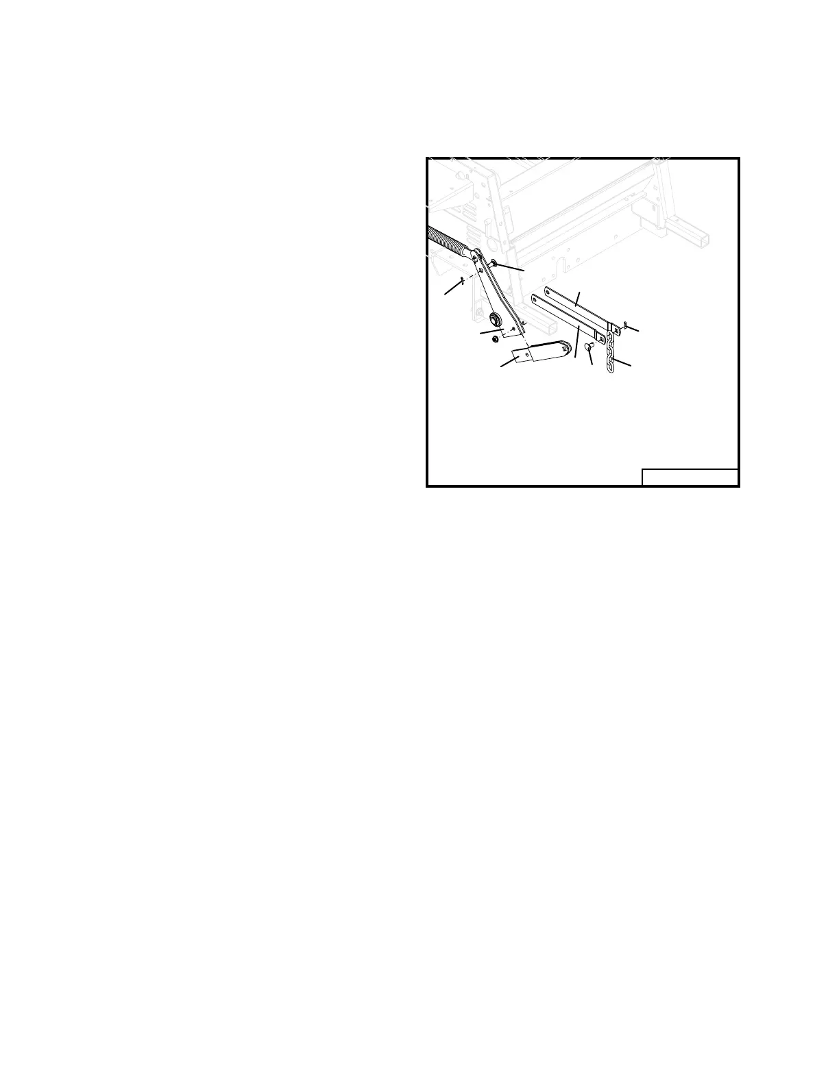
(refer to Fig. 5)
Remove the rocker arms (item 1) from the
rockers (item 2).
Remove the lift chain (item 3) from the
rocker arm.
Install lift straps (item 4) in the rocker secur-
ing with clevis pin (item 5) and cotter pin
(item 6).
Install lift chain (item 3) between lift straps
and secure with clevis pin (item 7) and cotter
pin.
Rev. 11-00
1
2
3
6
4
4
5
7
6
0 0 0 9 2
1 . R o c k e r A r m 5 . C l e v i s P i n
2 . R o c k e r 6 . C o t t e r P i n
3 . L i f t C h a i n - 5 l i n k s 7 . C l e v i s P i n
4 . L i f t S t r a p
WHEN INSTALLING SL98 SERIES
MOWER ON 700 OR 900 SERIES
TRACTOR
(refer to Fig. 6)
Locate and mount the right and left chain
guide brackets (item 6 and 7) to the lower
tractor frame as shown and secure each
bracket with two .375-16 x 1 whiz bolts
(item 1).
The bolts (item 4) securing the traction
springs to the rocker pivot arms should be
.375 x 1.375 carriage bolts. Older tractors
were equipped with a shorter clevis pins and
must be replaced.
Install the .25 inch spacer (item 2) on the car-
riage bolt.
Slide chain mount brackets (item 5) through
the slots in the chain guide brackets and se-
cure to .375 x 1.375 carriage bolt with lock
nut (item 3).
Mount the lift chains (item 8) to the mount
brackets and secure with cotter pins (item 9).
 Loading...