14
Fig. 9
0 0 0 4 6
T r a c t i o n K i t
T o o l
L i n c h
P i n
Mower mounting hole locations
Fig. 8
Rev. 11-00
Tractor Axle Bolt in Axle Bolt in
tire size lower hole upper hole
18" tires 4th hole* 3rd hole*
(600 series)
20" tires 3rd hole* 2nd hole*
(600 & 700
series)
21" tires 3rd hole* 2nd hole*
(700 series)
21" tires 2nd hole* Bottom hole
(700 & 900
G
2
series)
* from bottom hole
Rotate the deck mount latch pins 90° to a
closed position to lock the deck arm mount
clevises in place.
Raise the deck to the upright position (see
section "To Set Deck In Upright Position")
and attach the Lift Assist Spring (item 8, fig.
7) to the Spring Bracket (item 9). DO NOT
attempt to attach spring bracket with the
deck in the mowing (down) position.
Return deck to the mowing (down) position.
The spring will assist in lowering the deck.
Raise the deck stand to the up position.
Connect the PTO shaft ensuring the quick
disconnect is securely locked onto the
splined power shaft.
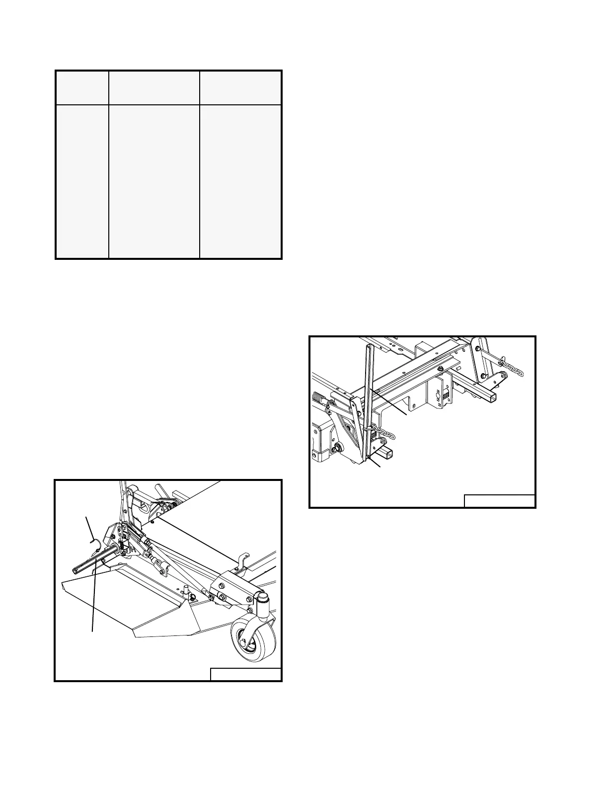
Attach the lift chains (item 5), from the trac-
tion kit, to the .375 x 2 clevis pins (item 6)
installed on deck. Use the traction kit tool to
extend the traction springs for easy installa-
tion. Refer to figure 9 and follow steps
below:
1. Position the notched end of the traction
kit tool over the hook on the chain guide
bracket.
2. Position tool so that the notched edges are
facing forward and the chain mount
bracket fits inside the notches.
3. Apply forward pressure on the upper end
of the traction kit tool. This will enable
you to extend traction springs to attach
lift chains to deck.
0 0 0 4 7 A
T r a c t i o n K i t
T o o l
H o o k
On 600 series tractor raise deck to upright
position to attach lift chain to mounting pin
(item 6, fig.7).
The pin (item 6) may need to be repositioned
to give proper traction kit chain alignment.
If this is necessary remove pushon retainer
and reverse pin position and reinstall re-
tainer.
 Loading...