WARNING
To be safe, always disconnect the transmitter battery before instal-
lation to avoid short circuit conditions.
Be sure to pay attention that soldered points on the transmitter board
do not come into contact with metal objects!
Unoccupied holes in the transmitter's housing are closed with
blind plugs. These can easily be pulled out from the outside.
Insert the accessory switch, etc. through a hole in the housing
from the inside.
Fixing the switch, switch module and knob module
The fixation is made by screwing a nut on the thread on the
upper part of the switch. These will pass though the housing and
tightened with a suitable wrench. The Graupner trim nut wrench
is well suited for tightening down these nuts.
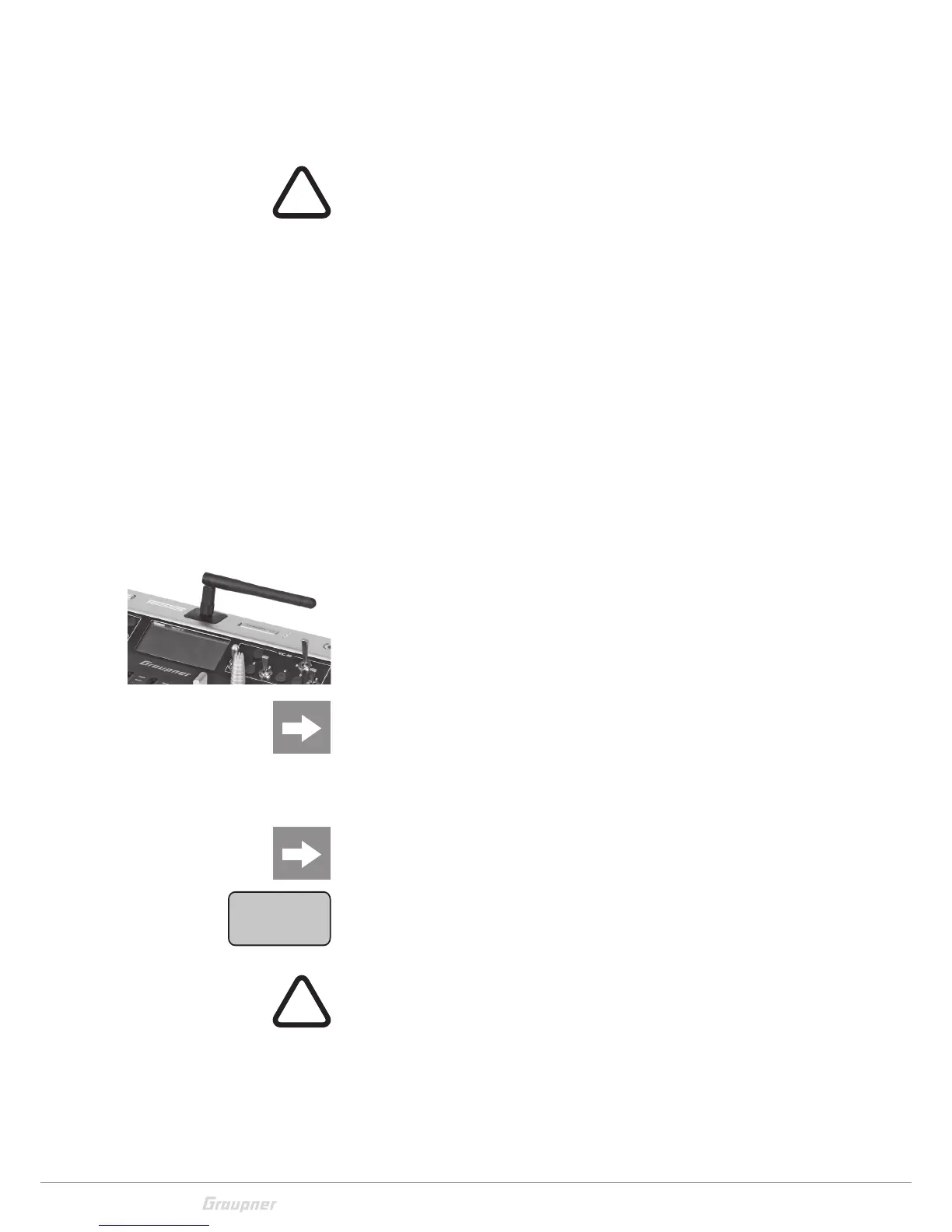
Aligning the antenna
The removable, articulated antenna is to be screwed into the
ball-joint connector then aligned by hand.
Do not point the antenna directly to the model. Turn and bend
the antenna so that during the use it is oriented to a side (see
picture on the left) or alternatively turn it perpendicularly to the
top.
CAUTION
When screwing in the antenna, pay attention that the centre pin in
the antenna socket does not get bent or pressed back in the socket.
Switch on transmitter
Safety query
When the transmitter is switched on the throttle position is checked.
(Premise: Model type "winged" "Motor at ch1 front/back" or model
type "Heli" is selected) If the throttle stick is set out of the minimum
position, the warning message "THR too high!" appears and the RF
module remains off for safety reasons.