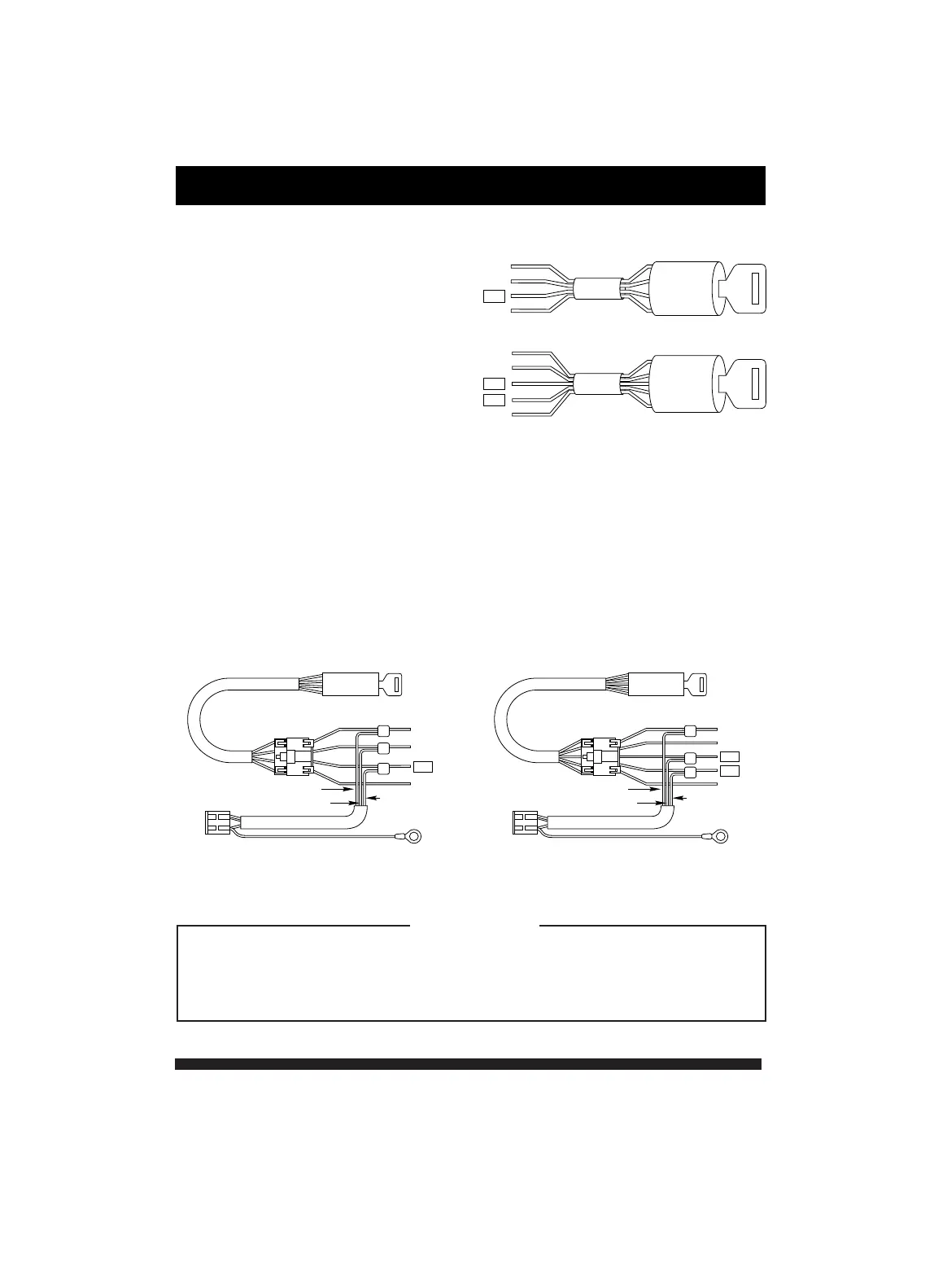
Wiring Diagram
The wires coming out form the key
switch usually consist of:
12 v - 12 volt constant power
ON - Ignition power
ACC- Accessory power
ST - Starter signal
Other than these four wires, the
vehicle may have two ON wires.
Wiring Procedure:
(1) Cut the Power harness close to the 3-pin connector
(2) Use a volt meter or test light to find the appropriate wires. Connect
the Red wire to the 12v, the Green to to ON, and the Blue to ACC
using solder.
(3) Cover all connections carefully with electrical tape.
Warning !
Green
Red
Blue
Black
Green
Red
Blue
Black
With vehicles that have 2 ignition (ON) wires, connect the Green wire
to the ignition (ON) wire which does not drop voltage when the starter
is activated. Then connect the Blue wire to the other ignition wire.
Warning
Standard Ignition
w/ 2 Ignition Wires
4
12V
ON
ACC
ST
12V
ON
ACC
ST
ON
12V
ACC
START
ON
12V
ACC
START
ON
ON