24
U-Match Series DC
Inverter Service Manual
DPOUSPM
3.2 Operation View
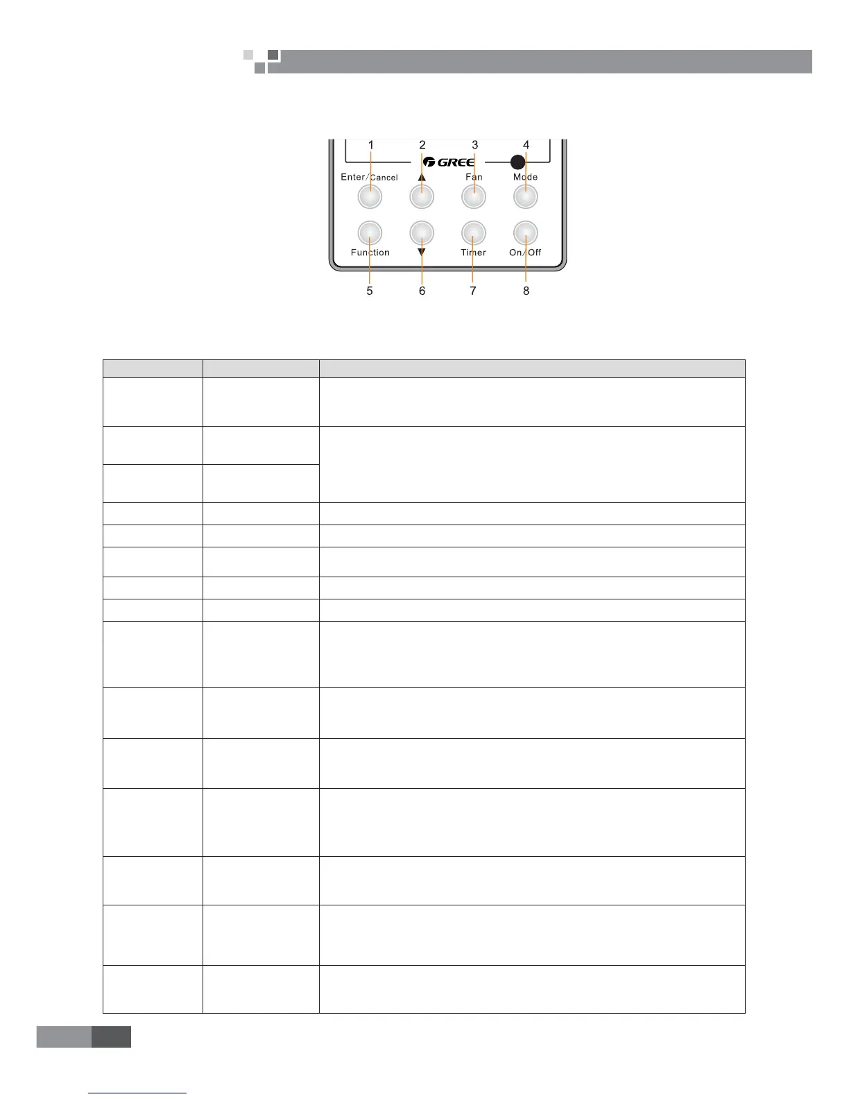
3.2.1 Silk Screen of Buttons
Figure 2-3-3 Silk screen of buttons
3.3.2 Instruction to Function of Buttons
Table 2-3-2 Instruction to buttons of wired controller
No. Description Functions
1 Enter/Cancel
ķ
Function selection and canceling;
ĸ
Press it for 5s to view the ambient temperature; press Mode button to select viewing
outdoor ambient temperature or indoor ambient temperature.
2 Ÿ
ķ
Running temperature setting range of indoor unit: 16-30°C;
ĸ
Timer setting range: 0.5-24hr;
Ĺ
Setting of air function level;
ĺ
Setting of energy-saving temperature;
Ļ
Setting of cleaning class.
6 ź
3 Fan Setting of high/medium high/medium/medium low/low/auto fan speed.
4 Mode Setting of auto/cooling/heating/fan/dry mode of indoor unit.
5 Function
Switch over among these functions of swing/air/sleep/health/ I-Demand/out/turbo/save/
e-heater/X-fan/clean/quiet.
7 Timer Timer setting.
8 On/Off Turn on/off indoor unit.
4 Mode
and
Ÿ
Memory function
3UHVV0RGHDQGŸ EXWWRQVDWWKHVDPH WLPHIRUVXQGHU RIIVWDWHRIWKHXQLW WRHQWHU
cancel memory function (If memory function is set, indoor unit will resume original setting
state after power failure and then power recovery. If not, indoor unit is defaulted to be off
after power recovery. Ex-factory setting of memory function is on).
Ÿ
and
ź
Lock
8SRQVWDUWXSRIWKHXQLWZLWKRXWPDOIXQFWLRQRUXQGHURIIVWDWHRIWKHXQLWSUHVVŸDQGź
buttons at the same time for 5s to enter lock state. In this case, any other buttons won’t
UHVSRQGZKHQSUHVVLQJ5HSUHVVŸDQGźEXWWRQVIRUVWRTXLWORFNVWDWH
4 Mode
and
5 Function
Enquiry and setting
of address of wired
controller
Under off state of the unit, press Mode and Function buttons at the same time for 5s to
set the address. (More details please refer to project debugging)
5 Function
and
7 Timer
Setting of project
parameters (More
details please refer to
the Notes)
Under off state of the unit, press Function and Timer buttons at the same time for 5s to
JRWRWKHGHEXJJLQJPHQX3UHVV0RGHEXWWRQWRDGMXVWWKHVHWWLQJLWHPVDQGSUHVVŸRU
źEXWWRQVWRVHWWKHDFWXDOYDOXH
4 Mode
and
ź
Switch between
Fahrenheit and
Centigrade
8QGHURIIVWDWHRIWKHXQLWSUHVV0RGHDQGźEXWWRQVDWWKHVDPHWLPHIRUVWRVZLWFK
between Fahrenheit and Centigrade.
5 Function
and
ź
Viewing historical
malfunction
&RQWLQXRXVO\SUHVV)XQFWLRQDQGźEXWWRQVIRUVWRYLHZKLVWRULFDOPDOIXQFWLRQ7KHQ
SUHVVŸDQGźEXWWRQVWRDGMXVWGLVSOD\HGFRQWHQWV7KHWLPHU GLVSOD\LQJSRVLWLRQ
displays the sequence of malfunction and the detailed error code. The 5
th
displayed
malfunction is the last malfunction.
1 Enter/Cancel
and
4 Mode
Setting of master and
slave wired controller
Under off state of the unit, press Enter/Cancel and Mode buttons at the same time for
VWRVHWPDVWHUDQGVODYHZLUHGFRQWUROOHU3UHVVŸRUźEXWWRQWRDGMXVW0RUHGHWDLOV
please refer to project debugging)
 Loading...