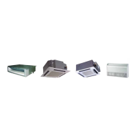
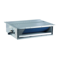
U-Match Series DC
Inverter Service Manual
,QVWDOOLQJWKH'UDLQ3LSHV
(1). For determining the position of the drain hose, perform the following procedures.
(2). Insert the drain pipe to the drain outlet of the unit and then tighten the clamp securely with tape. (Figure
(3). Connect the extension drain pipe to the drain pipe and then tighten the clamp with tape.
1 2
3
1
2
Drain pan
Seal
Drain hose
PP
)LJXUH)LJXUH)LJXUH
7LJKWHQWKHFODPSXQWLOWKHVFUHZKHDGLVOHVVWKDQPPIURPWKHKRVH)LJXUH
ķ
0HWDOFODPS
ĸ
'UDLQKRVH
Ĺ
*UH\WDSH
,QVXODWHWKHSLSHFODPSDQGWKHGUDLQKRVHXVLQJKHDWLQVXODWLRQVSRQJH)LJXUH
ķ
0HWDOFODPS
ĸ
,QVXODWLRQVSRQJH
(4). :KHQGUDLQKRVHUHTXLUHVH[WHQVLRQREWDLQDQH[WHQVLRQKRVHFRPPHUFLDOO\DYDLODEOH
After connecting the local drain hose, tape the slits of the heat insulation tube.
Connect the drain hose to the local drain pipe. Position the inter connecting wire in the same direction as
the piping.
&RQQHFWLQJWKH'UDLQ+RVH
(1). Connect the extension auxiliary pipe to the local piping.
(2). Prepare the local piping at the connection point for the drain pipe, as shown in the installation drawings.
Note: Be sure to place the drain hose as shown in the diagram below, in a downward sloping direction.
Drain pan
Drain hose
ķ
5LJKWVLGHSLSLQJ
ĸ
%RWWRPULJKWSLSLQJ
)LJXUH
7HVWLQJRI'UDLQ3LSLQJ
(1). $IWHUSLSLQJZRUNLV¿QLVKHGFKHFNLIGUDLQDJHÀRZVVPRRWKO\
(2). As shown in the figure, pour water into the drain pan from the right side to check that water flows
smoothly from the drain hose.
Ceiling type Floor type
)LJXUH
 Loading...