GMV5 D.C INVERTER MULTI VRF SERVICE MANUAL
224
wiring are correct. You are advised to replace them one after another.
NOTE:
Keep wiring identical to factory installation. Control varies with compressors. Wrong wiring
or inverse connection of the compressors may cause damage to units.
Cautions on replacement of compressors:
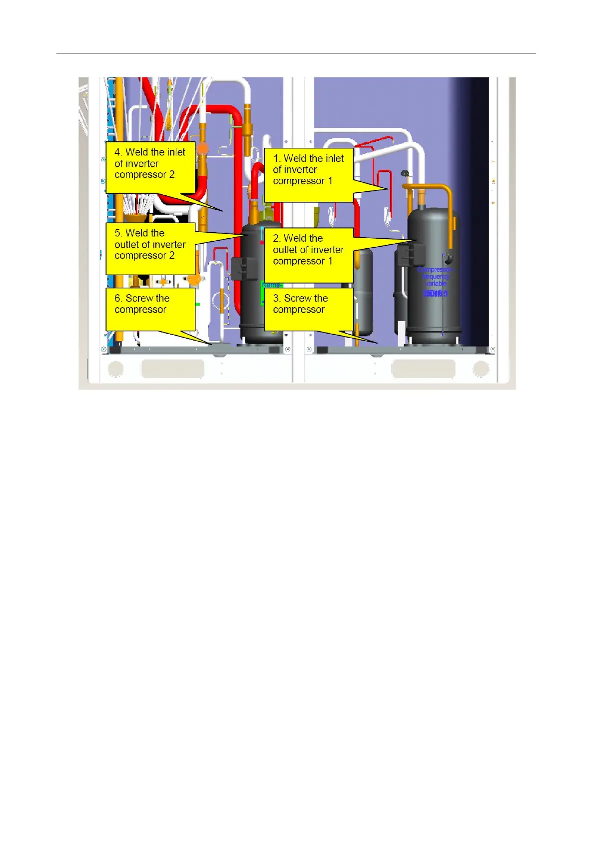
1) Before installing new compressors, remove the sealing rubbers and weld the compressors with
corresponding pipes. During welding, charge nitrogen into the pipes. Since compressors‘ suction and
discharge pipes are made of copper plated steels, you need to prepare special welding rods (containing
5% or more silver). Welding clearance should be controlled within 0.1~0.3mm, avoiding blockage or
loose welding. During welding, control pipe openings from being over-heated.
2) After the pipeline system is welded, use special supports and bolts to fix the compressors,
ensuring stability of the compressors during running.
3) Power lines of the compressors should be wired following the factory installation. You can refer
to the wiring diagram. Phase sequence error and inverse connection of compressors are not allowed.
Step 12: System check.
1) Check welding joints for abnormalities.
2) Charge nitrogen into the system for leakage detection. If you are maintaining ODUs and the IDU
system is normal, you can charge nitrogen into the ODU system only. Note that nitrogen should be
charged from both the high pressure side and low pressure side. You are advised to charge through all
valves. Nitrogen pressure should be larger than 2.0Mpa(290psi
)
. Then, charge soapsuds into the
system and check specially the weld joints for leakage.
3) Finally, charge nitrogen into the system again for pressure check. Close all valves and keep
 Loading...
