GMV5 D.C INVERTER MULTI VRF SERVICE MANUAL
378
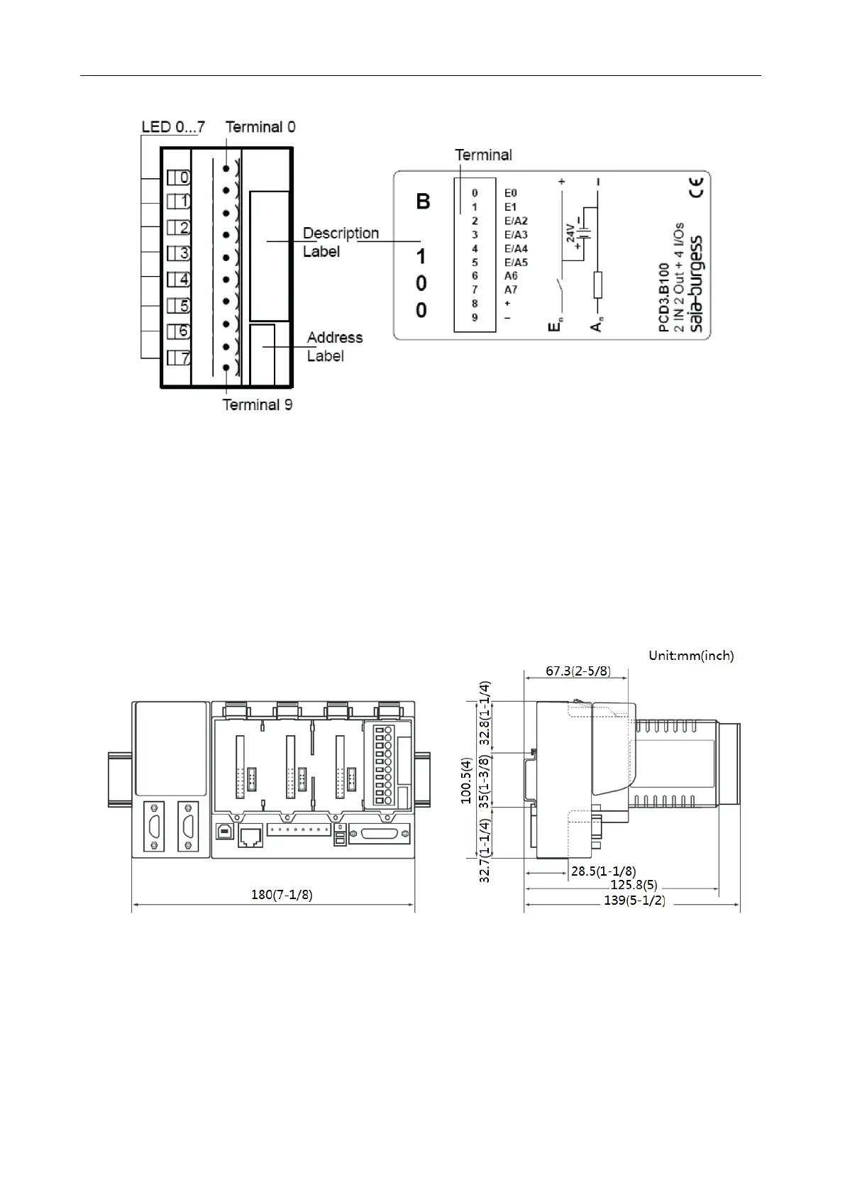
(4)I/O Module Indicating LED
As shown in the figure above, E0, E1, E/A2, E/A3 indicating LEDs are marks for four inputs and
E/A4, E/A5, A6, A7 indicating LEDs are marks for four outputs. Among them, when any one is the
high-level input/output, the corresponding LED will light on. (Voltage between each I/O and GND is 24V.
I/O is at the high level.)
2.2.4.4 Field Installation
(1)Hardware Installation
1. Outline Dimensions
 Loading...
