GMV DC Inverter VRF
55
debugging after setting.
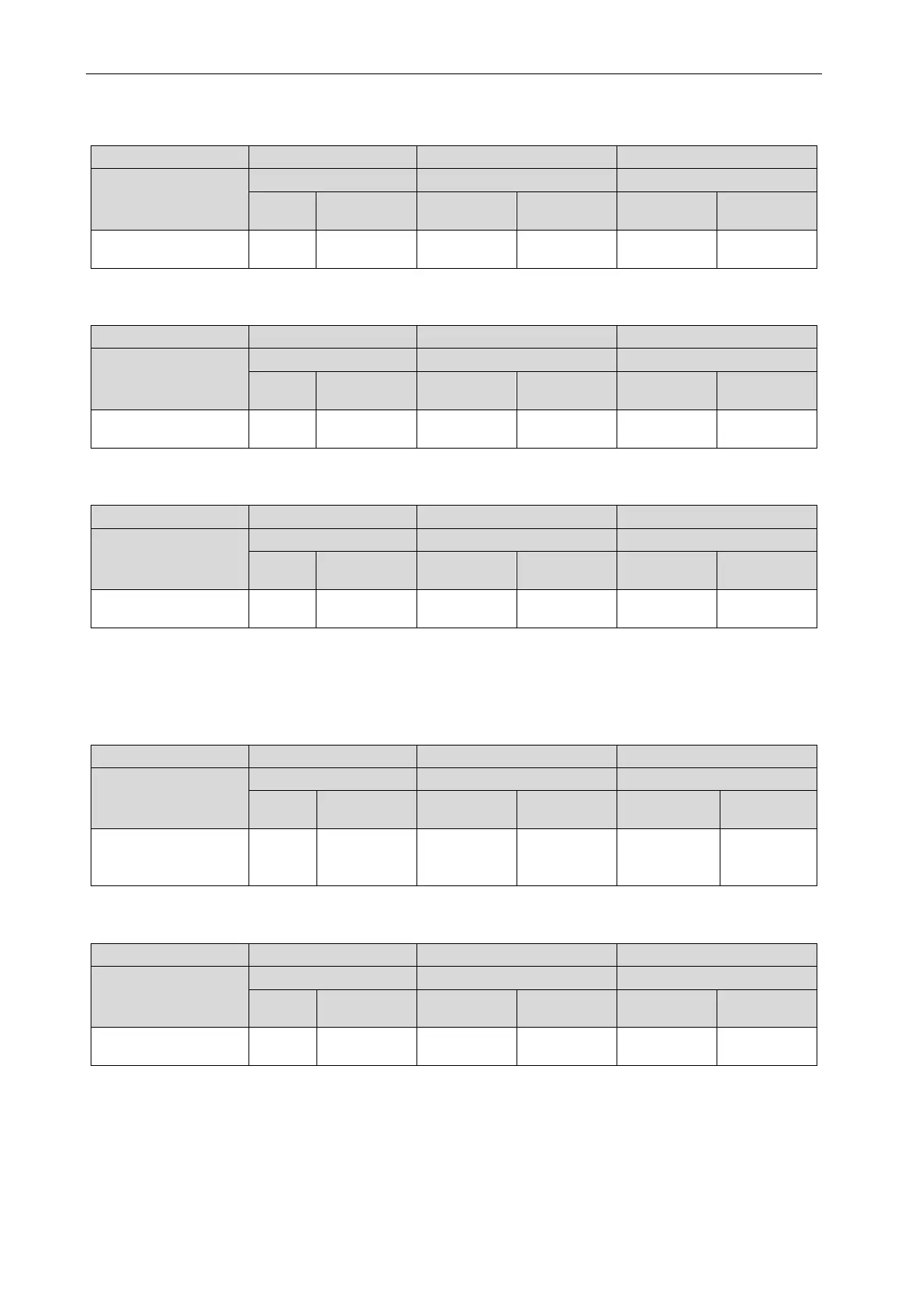
During the assignment process, all module digital tubes displays are as below:
Progress
Code
Display
Code
Display
Code
Display
02_allocate
db ON 02 ON Ad Flash
Step 6: When the unit is running to step 03, it displays the number of modules connected to the
outdoor connection. At this time, the main board of each module is displayed as below:
Progress
Code
Display
Code
Display
Code
Display
03_module quantity
db ON 03 ON
Module
Flash
After 30s of display, the automatic display is as follows; if press SW3 button within 30s, the display
is as follows. The unit automatically enters the next step of debugging:
Progress
Code
Display
Code
Display
Code
Display
03_module quantity
db ON 03 ON OC ON
Note:
It is important to confirm that the number of online outdoor unit modules is the same as that
of actual modules; otherwise it will need to conduct the inspection and debugging again.
Step 7: When the unit is running to step 04, the number of online connected indoor unit is
displayed. At this time, the main board of each module is displayed as below:
Progress
Code
Display
Code
Display
Code
Display
04_indoor unit
quantity confirmation
db ON 04 ON
The quantity
of online
Flash
After 30s of display, the display is as follows; if press SW3 button within 30s, the display is as
follows. The unit automatically enters the next step of debugging:
Progress
Code
Display
Code
Display
Code
Display
04_indoor unit
db ON 04 ON OC ON
Note:
It is important to confirm that the number of online indoor unit modules is the same as that
of actual connected indoor units for the project; otherwise it will need to conduct the inspection and
debugging again.
Step 8: Step 05 of the unit debugging is “detect internal communication”.
If there is no abnormality in the detection, the display is below, and then it automatically enters
the next step of detection.
 Loading...
